/
Investigation of a Blazed Reection Grating Daniel E Investigation of a Blazed Reection Grating Daniel E

Investigation of a Blazed Reection Grating Daniel E - PDF document

celsa-spraggs
celsa-spraggs . @celsa-spraggs
Follow
405 views
Uploaded On 2015-05-06

Investigation of a Blazed Reection Grating Daniel E - PPT Presentation

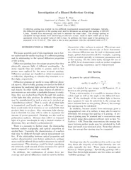
Shai Department of Physics The College of Wooster Wooster Ohio 44691 USA Dated May 9 2004 A re64258ection grating was studied via two di64256erent experimental measurement techniques Initially the di64256ractive properties of the grating were used t ID: 61979

Shai Department Physics

Share:

Link:

Embed:

Download Presentation from below link

Download Pdf The PPT/PDF document "Investigation of a Blazed Reection Grati..." is the property of its rightful owner. Permission is granted to download and print the materials on this web site for personal, non-commercial use only, and to display it on your personal computer provided you do not modify the materials and that you retain all copyright notices contained in the materials. By downloading content from our website, you accept the terms of this agreement.


Presentation Transcript

2Twoprominentmethodsofmanufacturinggratingsareviaeitherrulingorholographictechniques.Inbothcases,averyaccurate\master"gratingismadeandthensubse-quentgratingsarereproducedfromthismastertemplate.Ruledgratingstakeontheformofasawtooth,whileholographicgratingsmorecloselyresemblesinewaves.Forasawtoothgrating,theanglebetweenthelongsideoftheruledsurfaceandtheplaneofthegratingisknownastheblazeangle.Itisthisanglethatdeterminesintowhichorderthedi ractedlightwillbedirected.Holo-graphicgratings,ontheotherhand,cannotbeblazedaseasilyandthereforeproducemuchlowerecienciesthanruledgratings.Whenthewavelengthoftheincidentlight,however,isontheorderofthegratingspacing,theeciencyincreasestothepointthatitiscomparabletothatofaruledgrating.Thiswavelengthofmaximumeciencyiscalledtheblazewavelength.FortheOrielgratingusedinthisexperiment,theblazewavelengthis250nm.[6]Forasinusoidallyshapedholographicgrating,theblazeangleisde nedastheangleatwhichboththeincidentlighthitsthegratingandthedi ractedlightisre ected,relativetothegratingnormal,whentheinci-dentlightwavelengthisequaltotheblazewavelength.[7]Inotherwords,theblazeangle istheanglethatsat-is esequation(1)forbothinandmfor=b,andmisorderofwhichevermaximatowhichthelightisdirected.Forthegratingusedinthisexperiment,themanufacturerhasprovidedthatthegratingdirectsthemajorityofthelightintensityintothe rstorderandthatb=250nm.Wemaythencalculatetheblazean-glenecessarytodi ractthelightintensityintothe rstorder(m=1),beginningwiththegratingequation:sin(m)+sin(in)=m dsin( )+sin( )=1b d =arcsinb 2d:(2)EXPERIMENTThisequipmentusedinthisexperimentincludedaDi-mension3100AFM,anOriel77230re ectiongrating,andanopticalspectrometer.TheOrielre ectiongratingwas rststudiedbyatomicforcemicroscopy.TheAFMwastestedusingawafercontainingagridof55mwells.There ectiongratingwasthenscanned.Severalscansweretakenwithsizesofboth55mand11m.Thegratinghadbeenpreviouslyused,andwasthereforesomewhatscratched.Carewastakennottoscananareathatwasexessivelyscratched.TheAFMwascontrolledusingthenanoscopesoftware.Thegratingswerescannedsuchthatthetipmovementwasneverparalleltothegratingruling.DatacollectedfromthesescanswasthenimportedintothecomputerprogramIgorProCarbonv.4.05foranalysis.Theopticaldi ractivepropertiesofthegratingwerethenstudied.Aspectrometerwasusedinordertode-terminetheangleofincidenceandofdi ractionforthegratingtothenearestminuteofarc.ThelightsourcewaschosentobeaMercurylamp,becauseitemitsmul-tiplediscretewavelengthsoflight.Thisway,multipledi ractionmaximawereobserved.Theanglesoftheze-rothand rstorderdi ractionmaximawererecordedformultiplewavelengthsoflight.Fivemeasurementsweremadeforeachmaximainordertoensurereproducibility.Eachtime,thespectrometerapproachedthepeakfromtherightsoastominimizethepossibilityofsystematicerror.RESULTSANDANALYSISLineSpacingBecausethegratingwasproducedbyholography,itssurfaceshouldbeshapedasasinewave.Thus,anaver-ageestimateofthefrequencyofoscillationmaybedeter-minedby ttingasinewavetothecross-sectionalAFMdataasshowninFigure1.Thecrosssectionwaschosensothatwelookalmostdirectlydownthelengthofthegratinglines.Inotherwords,we\cut"perpendiculartothegratinglines.Thus,localinconsistenciesareaver-agedoutofthedata,andtheaveragedistancemaybedeterminedusingthefrequencyofoscillation.ThisdataissummarizedinTableI. FIG.1:Asinewave ttedtothecrosssectionofascan.Usingequation(1),theanglesmeasuredusingthespectrometermaybeused,alongwiththewavelengthsoflightemittedbytheHglamp,todeterminethedis-tancebetweengratinglinesdandthusthelinesspacingS.TheseresultsaresummarizedinTableII.BlazeAngleThegratingstudiedherewasfabricatedsuchthatthereare2400lines/mm.Thisspeci cationcorrespondstoa 3TABLEI:Spacingdataforthethreere ectiongratingscansamples,asdeterminedbysinewave ts. Scan# Spacing(Lines/mm) 1 24244 2 23152 3 23152 Average 235151() TABLEII:Summaryoflinespacingasdeterminedbyopticaldi raction. Trial Sspacing(Lines/mm) 1 24006 2 24006 3 24006 4 24036 5 24016 Average 24016 linespacingd=416:7nm.Byplotting asafunctionofb,usingequation(2)form=1,weobtainawaytodeterminetheblazeanglefromthemanufacturer'sblazewavelength(Figure2). FIG.2:Agraphofblazeangle, ,versusblazewavelength,b.Byusingthemanufacturer'svaluefordandb,wemaysolveequation(2)fortheblazeangle .Forthegratingusedinthisexperiment, =17:5.Aspreviouslymentioned,foraruledre ectiongrating,theblazeangle whicha ectstowhichorderlightisdirectedisde nedastheanglebetweenthelongfaceofthesawtooth-shapedsurfaceandtheplaneofthegrating.Withaholographicgrating,thesurfaceisshapedasasinewave.Byusingthede nitionoftheblazeangleforaruledgrating,wemayapproximatetheblazeangleforaholographicgratingbyassumingthatthesinewaveisapproximatelyatriangularwave.AsillustratedinFigure3,ifwemakethisassumption,calculationoftheblazeanglebecomespossible. FIG.3:Approximateblazeangleforaholographicgrating.Ifweassumethattheheightofthe\triangle"issimplytheheightofthesinewave,thentheverticalsideofthetriangleissimplytwicetheamplitude.Also,wemayassumethatthewidthofthetriangleisonehalfoftheperiodofthewave.Usinggeometry,wemaycalculatetheapproximateblazeangle:tan =2A d=2 =arctan4A d(3)UsingEquation(3)theaprroximateblazeanglewascal-culatedforthebest- tsinewavesgeneratedpreviouslyto ndthespacingd.TheseresultsaresummarizeinTableIIITABLEIII:Spacingdataforthere ectiongrating,asdeter-minedbyasinewave t. ScanFilename (degrees) `refgrat2.004' 12:40:1 `refgrat2.007' 12:80:2 `refgrat2.009' 11:90:2 Average 12:40:4() Thecalculatedvalueof17:5isconsistentlylargerthanthoseapproximatedusingatomicforcemicroscopy.Thisdi erencecouldbecausedbythreesources.First,itispossiblethatsomesortofsystematicerrorwasinvolvedintheAFMmeasurement.TheAFMwasperhapsnotcalibratedproperly.Inaddition,asecondsourceoferrorcouldbethesteepnessofthegratinglines.Whenthetiptravelsalongthegratingsurface,itcannotaccuratelymeasuresteepslopes.Thistypeoferrorwouldresultin