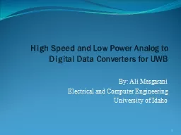
OnChip Global Link Using ContinuousTime Linear Equalizer Yulei Zhang 1 James F Buckwalter 1 and Chung Kuan Cheng 2 1 Dept of ECE 2 Dept of CSE UC San Diego La Jolla CA ID: 419434
Download Presentation The PPT/PDF document "High-Speed and Low-Power" is the property of its rightful owner. Permission is granted to download and print the materials on this web site for personal, non-commercial use only, and to display it on your personal computer provided you do not modify the materials and that you retain all copyright notices contained in the materials. By downloading content from our website, you accept the terms of this agreement.
Slide1
High-Speed and Low-Power On-Chip Global Link Using Continuous-Time Linear Equalizer
Yulei Zhang
1
,
James F. Buckwalter
1
, and Chung-
Kuan
Cheng
2
1
Dept. of ECE,
2
Dept.
of CSE,
UC San Diego, La Jolla, CA
19
th
Conference on Electrical Performance of Electronic Packaging and Systems
Oct
25, 2010
Austin,
USASlide2
2
Outline
Introduction
Equalized On-Chip Global Link
Overall structure
Basic working principle
Driver Design for On-Chip Transmission-Line
Guideline for tapered CML driver
Driver design example
Continuous-Time Linear Equalizer (CTLE) Design
CTLE modeling
CTLE design example
Driver-Receiver Co-Design for Low Energy per Bit
Methodology
Overall link design example
ConclusionSlide3
Research Motivation
Global interconnect planning becomes a challenge in ultra-deep sub-macron (UDSM) process
Performance gap between global wire and logic gates
Conventional buffer insertion brings in larger extra power overhead
Uninterrupted wire configurations are used to tackle the on-chip global communication issues
On-chip T-lines to reduce interconnect power
Equalization to improve the bandwidthState-of-the-art[Kim2009]2Gb/s/um, < 1pJ/b, signaling over 10mm global wire in 90nm
3Slide4
Our Contributions
Contributions
Build up a novel equalized on-chip T-line structure for global communication
Tapered CML driver + CTLE receiver
Accurate small-signal modeling on CTLE receiver to improve the optimization quality
A design methodology to achieve driver-wire-receiver co-optimization to reduce the total energy per bit
Results of our design20Gbps signaling over 10mm, 2.2um-pitch on-chip T-line11ps/mm latency and 0.2pJ/b energy per bit in 45nm
4Slide5
Equalized On-Chip Global Link
5
Overall structure
Tapered current-mode logic (CML) drivers
Terminated differential on-chip T-line
Continuous-time linear equalizer (CTLE) receiver
Sense-amplifier
based latchSlide6
Basic Working Principle
Tapered CML Driver
Provide low-swing differential signals to driver T-line
Tapered factor
u
, number of stages
N, fan-out X, final stage current ISS, driver resistance R
S
T-line
Differential wire w/ P/G shielding
Geometries
(width, pitch)
and termination resistance
R
T
CTLE Receiver
Recover signal and improve eye-qualityLoad resistance RL, source degeneration resistance RD and capacitance CD, over-drive voltage Vod.Sense-amplifier based latchSynchronize and convert signal back to digital level
6Slide7
Tapered CML Driver Design
Output swing constraint
Design guideline
[Tsuchiya2006, Heydari2004]
Begin from the final stage
For given
VSW, output resistance RS optimized with RT to increase eye-openingTransistor sizeTapered factor
u
= 2.7 for delay reduction
Number of stages
Each previous stage is designed backward by scaling with the factor
u
7
Need to design:
Output resistance
R
S
Tail current
I
SS
Size of transistors
WSlide8
CML Driver Study w/ Loaded T-line
8
Assume 45nm 1P11M CMOS
T-line built on M9 with M1 as reference
T = 1.2um, H = 3.5um (fixed)
Optimize W and S for eye-opening
Change of the eye-opening with
width
for
fixed 2um pitch
Change of the eye-opening with
pitch
for
equal width/spacing Slide9
CML Driver Design Example
Experimental observations
Optimal eye happens when width=spacing
Eye-opening improves with larger pitch
Design methodology
Choose
the minimum pitch that satisfied the wire-end eye-opening requirement Design example9Slide10
Accurate CTLE Modeling
10
Small Signal Circuit to derive H(s):
Design Variables:
R
L
, R
D
, C
D
,
V
od
(Size)
[Hanumolu2005]Slide11
CTLE Modeling Validation
Test case:10mm, 16mV-eye@wire-end
Blue lines: simple modeling, not consider
r
ds
and
parasiticsRed line: only consider rds
Black line: the proposed accurate model
11
<10% correlation error
>20% eye-opening increaseSlide12
CTLE Design Example
Observations of CTLE study
Eye-opening improves with relaxed power constraints but tends to be saturated
Design example
Based on the pre-optimized
CML driver + T-line
designEye-opening improved by 4X after CTLE12Slide13
Driver-Receiver Co-Design
Methodology
Optimize driver-wire-receiver together by setting
Veye
/Power
as the cost function
Choose pre-designed CML/T-line/CTLE as initial solution Optimization FlowDriver-to-receiver step-response generation based on SPICE simulation and CTLE modelingEye-opening estimation based on step-responseSQP-based non-linear optimizationVariables: [I
SS
,R
T
,R
L
,R
D
,C
D
,Vod]Performance ComparisonOption A:Driver/Receiver independent designOption B:Low-power driver/receiver co-design13Slide14
Low Energy-per-Bit Optimization Flow
14
Pre-designed CML driver
Pre-designed CTLE receiver
Driver-Receiver Co-Design Initial Solution
Co-Design Cost Function Estimation
SPICE generated
T-line step response
Step-Response Based Eye Estimation
Receiver Step-Response using CTLE modeling
Internal SQP (Sequential Quadratic Optimization) routine to generate best solution
Best set of design variables in terms of overall energy-per-bit
Change variables
[
I
SS
,R
T
,R
L
,R
D
,C
D
,V
od
]
Cost-Function
Veye
/PowerSlide15
Simulated Eye Diagrams
15
Methodology A: driver/receiver separate design
Methodology B: driver/receiver co-design for low-powerSlide16
Summary of Performance Comparison
Methodology
A
driver/receiver separate design
Methodology
B
driver/receiver co-design for low-powerRS/ohm47148
R
T
/ohm
94
1100
R
L
/ohm
440
890RD/ohm1101430CD/
fF
680
150
V
od
/mV
60
58
Eye-
Opening@CTLE
/mV
91
113
Power
Consumption/
mW
8.1
3.8
16
Note: driver/receiver co-design methodology uses much larger driver/termination resistance to reduce power, but will close the eye-opening
at the driver output and wire-end. Final eye is recovered by fully utilizing CTLE.Slide17
Conclusion
We propose a novel equalized on-chip global link using CML driver and CTLE receiver
Accurate modeling for CTLE is provided to achieve <10% correlation error and will improve eye-opening optimization quality
Our design achieves
20Gbps signaling over 10mm, 2.2um-pitch on-chip T-line
11ps/mm latency and 0.2pJ/b energy
17Slide18
Thank You!
Q & A
18