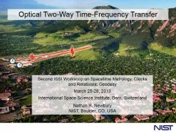
Second ISSI Workshop on Spacetime Metrology Clocks and Relativistic Geodesy March 2528 2019 International Space Science Institute Bern Switzerland Nathan R Newbury NIST Boulder CO USA Team ID: 760487
Download Presentation The PPT/PDF document "Optical Two-Way Time-Frequency Transfer" is the property of its rightful owner. Permission is granted to download and print the materials on this web site for personal, non-commercial use only, and to display it on your personal computer provided you do not modify the materials and that you retain all copyright notices contained in the materials. By downloading content from our website, you accept the terms of this agreement.
Slide1
Optical Two-Way Time-Frequency Transfer
Second ISSI Workshop on Spacetime Metrology, Clocks and Relativistic Geodesy
March 25-28, 2019
International Space Science Institute, Bern, Switzerland
Nathan R. Newbury
NIST, Boulder, CO, USA
Slide2Team
Laura Sinclair, Jean-Daniel Deschenes
*,
Hugo Bergeron, William Swann, Isaac Khader, Martha Bodine, Esther Baumann, Fabrizio Giorgetta, Paritosh Manurkar, Sarah Stevenson, Jennifer Ellis, Emily Hannah, Nate Newbury
*
Octosig
Slide3Optical
TWTFT
Optical
TWTFT
~
~
Remote
site
~
Master Optical Oscillator/Clock
Femtosecond Clock Network
Some uses:
Time/frequency dissemination
Distributed coherent sensing (active or passive)
Navigation (high precision &
gps
denial)
Secure communications
….
quartz oscillator
or
optical cavity
Goal: enable future femtosecond clock network
Slide4Outline
Introduction
Turbulence
Comb-Based OTWTFT: basic system and results
Overview of configurations and tests conducted
Conclusion
Slide5Our Clock
Cavity-stabilized
laser
Self-referenced
comb
Ticks @ 5 ns
fs
locked to underlying oscillator
Controller:
Count and “label” pulses
Define this pulse arrival at reference plane as
12:00:00.000000000000000
Reference plane
Comb
Quartz/DRO
10 GHz oscillator
Clock
Atoms
rarely
Slide6Free-space transfer:
Turbulence, platform motion…
Clock
Frequency
Comb
Frequency
Comb
Clock
Amplitude noise & signal loss
From turbulence (scintillation & beam wander)
From obstructions & platform motion
Well-known from free-space optical communications
Phase noise (time-of-flight variations)
From turbulence (“piston effect”)
From platform motion
1st
order Doppler shifts -> Need less than 3 nm/sec to reach
v/c
<
Atmospheric Turbulence:
“textbook” Kolmogorov scaling
Inertial
“Kolmogorov scaling”
Dissipative
k
< 1/l0
Input
k
< 1/L0
From Andrews, Phillips, and Hopen “Laser Beam Scintillations with Applications”, SPIE Press (2001)
Spatial power spectrum of index fluctuations
wavevector (k)
Outer Scale
Inner Scale
density variations -> index of refraction variations -> random phase mask -> time of flight variations
Inertial range
Slide8Temporal Power Spectral Density of Timing Jitter
Taylor’s Frozen Turbulence Hypothesis
Predicted Timing Jitter
Outer scale L
0
= 10 m
C
n
2
= 1x10-14 m-2/3 vx = 1 m/s
Standard assumption(Van Karman)
GT spectrum*
Kolmogorov scaling~ f -8/3
wind (
v
x )
~ vx/2pL0
input region
inertial region
*Greenwood and
Tarazano
, 1974
Slide9Clock
Frequency
Comb
Frequency
Comb
Clock
But the link is still reciprocal
Turbulent Atmosphere is reciprocal
*
For
two-way
single-mode
link, time-of-flight variations are common mode
* J. Shapiro
J. Opt. Soc. Am.
61
492 (1971); J. Shapiro & A.
Puryear
,
J. Opt.
Commun
.
Netw
.
4
947 (2012); R. R.
Parenti
et al.,
Opt. Exp.
20
21635 (2012)
(not true for a multi-mode link)
Slide10Two-Way Time Transfer: Basic Concept
Timer
Site B
Site A
t
A
=0
t
A→B
=
T
link
+
D
t
AB
t
B→A
=
T
link
-
D
t
AB
t
B
=0
Timer
Requires a “Reciprocal” Link
A single-mode optical link is reciprocal!
—
Clock Time Offset
D
t
AB
Slide11Two-Way Time Transfer + Feedback
Synchronization
Timer
t
A→B
t
B→A
Timer
feedback
Site B
Site A
Real-time calculation
Communication link
—
D
t
AB
Slide12Two-Way Time Transfer: With Combs
Timer
Site B
Site A
t
A→B
=
T
link
+
D
t
AB
t
B→A
=
T
link
-
D
t
AB
Timer
Comb timing is at femtosecond level!
But timing information lost in
photodetection
…still picosecond level timing
Slide13Comb 2
Comb 1
Pulses from Comb A “downsample” pulse train from Comb B
Digitizer
f
rep,A
Time”
Ampl.
f
rep,B
D
f
r
Interferogram:
Cross-correlation
Downsampled pulse train
Our system:
T
Red
= 10 ns = 1/100 MHz
d
T = 300 fs
d
T/ T
Red
=30,000
(Downsampling factor)
Dual Comb Measurement Technique
Slide14Interferogram
(cross-corr.)
Comb
Comb
x
x
x
x
x
x
x
x
x
x
x
x
x
x
x
x
x
x
x
x
x
x
x
x
x
x
x
x
x
x
time
x
x
x
x
x
x
x
x
x
x
x
x
x
x
x
x
x
x
x
x
x
x
x
x
x
x
x
x
x
x
x
x
x
x
x
x
x
x
x
x
x
x
x
x
x
x
x
x
x
x
x
x
x
x
x
x
x
x
x
x
d
t
clock
Small timing shifts are “amplified” in the interferogram spacing by
(
f
r
/
D
f
r
= 100,000)
Detection of Pulse Arrival with Femtosecond Precision
Analogous to high-speed Sampling Oscilloscope
1/
D
f
r
1/
D
f
r
1/f
r1
1/f
r2
Comb 1
Comb 2
1/
D
f
r
+
d
t
clock
(
fr
/
D
f
r
)
Combs phase-locked to clock
with differing repetition rate,
D
f
r
= f
r1
– f
r2
Slide15Controller
Controller
Comb Pulse Arrival Detection
“Linear Optical Sampling” approach
Time offset at 2kHz update with femtosecond precision but
5
nanosec
ambiguity (which comb pulse?)
Clocks tick at different rates…cannot “synchronize”
Purposefully run clocks at different rates
Site B
Site A
(
f
r
+
D
f
r
)
-1
f
r
-1
Linear sampling of Comb A arrival by Comb B
t
B→A
Linear sampling of Comb A arrival by Comb B
t
A→B
—
Clock Time Offset
D
t
AB
Slide16Comb-based Synchronization System
Controller
Controller
Coarse Two-way &
Comms
Transfer Comb
CW Laser Coherent TX/RX
Coarse Two-way &
Comms
Synch.
Equation
Comb-based timing measurement
Three signals between sites:
Phase modulated
cw
light for “coarse” two-way timing
Comb light for “fine” two-way timing
Coherent communication (to close the loop)
Plus full calibration of each terminal delays for “absolute” time
Timing Exchange
Remote Comb
Master Comb
Clock Output
Clock
Output
10-100 Hz
Feedback BW
Slide17Comb-based Synchronization System
Timing Exchange
Out-of-Loop
Verification
Clock Output
Clock Output
Slide18Experimental Setup for 4 km Folded Link Across the NIST Campus
Free-space terminals
FPGA controllers
Frequency comb transceivers
~5
mW
launch
Slide19Turbulence-induced beam pointing and scintillation
Slide20One-way (time-of-flight) vs. Two-way (clock timing)
Two-way:
T
AB
Two-way (TAB): x2000 expanded view
Clock Timing (fs)
Time Variation (psec)
Air Temperature (C)
One-way (DTA)
Suppression of variations in path length to fsec level
Slide21Residual Frequency Uncertainty
90% Link availability
Shorted-path
Optical Clocks
Also … No Systematic Bias
at the 2.6x10
-19
Level
Slide22O-TWTFT: Experiments
Carrier-Phase OTWTF
for u
ltra-precise clock comparisons
Sub-fs clock Synchronization with 25 m/s Motion
Coherent 10 GHz – Synched Microwave Osc.
Multi-Node network
Simplified PicosecondSynchronization
Modifications to support ultra-long distance links*
Limits to FutureGround-to-Satellite Links
O-TWTFT
Synchronization Across 12 km of Air
Completed
Under Investigation
Comparison of Atomic Optical Clocks
Applications to Coherent Sensing?
* over 1-10 km-scale testbeds
Slide23O-TWTFT: Over strong turbulence
Ultra-precise clock comparisons
~ 1e-17 @ 1 sec
Sub-fs clock Synchronization with 25 m/s Motion
Coherent 10 GHz – Synched Microwave
Osc.
Multi-Node network
Simplified PicosecondSynchronization
Modifications to support ultra-long distance links**
Limits to FutureGround-to-Satellite Links
O-TWTFT
Synchronization Across 12 km of Air
Completed
Under Investigation
Comparison of Atomic Optical Clocks
Applications to Coherent Sensing*
*At white paper level
** over 1-10 km-scale testbeds
Slide24Synchronization Across 12 km of Strong Turbulence
NIST
Valmont
Butte
5.8 km
Collaborated with JH APL to verify compatible with Adaptive Optics Terminals
Same results for “tip/tilt” terminals
and Adaptive Optics terminals
Path: 12 km highly turbulent path o
ver
a City
Slide25Turbulence Causes many short Dropouts
Dropout = period during which received power is below ~2.5
nW threshold
Strong turbulence
Moderate turbulence
Most turbulence-induced dropouts are < 10
ms
Increased turbulence increases the number of dropouts
12 kilometer
Slide26Synchronization Across 12 km of Strong Turbulence
Time Deviation
Averaging Time (s)
100 fs
1 fs
10 fs
100 as
1
10
100
1000
0.1
NIST
Valmont
Butte
5.8 km
L. Sinclair, Applied Physics Letters,
109, 151104 (2016).
Path: 12 km highly turbulent path o
ver
a City
Continuous
Gated
Slide27Carrier-Phase OTWTF for u
ltra
-precise clock comparisons
Sub-fs clock Synchronization with 25 m/s Motion
Coherent 10 GHz – Synched Microwave Osc.
Multi-Node network
Simplified PicosecondSynchronization
Modifications to support ultra-long distance links*
Limits to FutureGround-to-Satellite Links
O-TWTFT
Synchronization Across 12 km of Air
Completed
Under Investigation
Comparison of Atomic Optical Clocks
Applications to Coherent Sensing?
* over 1-10 km-scale testbeds
O-TWTFT: Comparison of Atomic Optical Clocks
Slide28On-Going Work: Comparing Atomic Optical Clocks
Comparison of state-of-the-art Sr and Yb Atomic Clocks in the 10-18 Range
Yb
clock
Sr clock
O-TWTFT
fiber
link
NIST
U. of Colorado
Large NIST collaboration
See Dave L. Talk later in workshop
Slide29Carrier-Phase OTWTF for u
ltra
-precise clock comparisons
Sub-fs clock Synchronization with 25 m/s Motion
Coherent 10 GHz – Synched Microwave Osc.
Multi-Node network
Simplified PicosecondSynchronization
Modifications to support ultra-long distance links*
Limits to FutureGround-to-Satellite Links
O-TWTFT
Synchronization Across 12 km of Air
Completed
Under Investigation
Comparison of Atomic Optical Clocks
Applications to Coherent Sensing?
* over 1-10 km-scale testbeds
O-TWTFT: Carrier-Phase OTWFT
Slide30Using Phase for Higher Timing Precision
Optical phase is more sensitive (but has 5 fs ambiguity)
1
ps
5 fs
envelope uncertainty
phase fringe uncertainty
Combine for high precision and no ambiguity…
Slide31t
A
Q
A
t
B
Q
B
Oscillator B
Comb
Oscillator A
cavity
laser
fiber link
Two-way carrier-phase extraction
Relative timing
Carrier-Phase OTWTFT
Slide32Carrier Phase OTWTFT Allows Frequency Comparisons at 10
-17 level @ 1 sec
Previous OTWTFT (pulse envelope only)
Carrier phase OTWTFT
10X-30X improvement to 10
-17
@ 1 second
L. Sinclair et al., Physical Review Lett, 120, 050801 (2018)
Very near limit set by time-dependent turbulence
Slide33Timing
(femtosec)
Optical phaseDifference (rad)
Tracking relative timing/phase wander between sites without error
Truth data
Difference (at 0.5
ms
sampling) (at 1-s smoothing)
In phase, unwrapped 300 million radian phase wander without a single
p
error
(post processing but real-time should be possible)
OTWTF phase/timing data
Slide34O-TWTFT: Sub-fs Clock Synchronization with motion
Ultra-precise clock comparisons
~ 1e-17 @ 1 sec
Sub-fs clock Synchronization with 25 m/s Motion
Coherent 10 GHz – Synched Microwave
Osc.
Multi-Node network
Simplified PicosecondSynchronization
Modifications to support ultra-long distance links**
Limits to FutureGround-to-Satellite Links
O-TWTFT
Synchronization Across 12 km of Air
Completed
Under Investigation
Comparison of Atomic Optical Clocks
Applications to Coherent Sensing*
*At white paper level
** over 1-10 km-scale testbeds
Slide35Clock
Frequency
Comb
Frequency
Comb
Clock
What About Moving Platforms?
Relative velocity of
3 nm/sec →
v
/c
<
Relative motion of 300 nm
→
1 femtosecond
Turbulence still present -> signal fades & piston noise
Platform motion worse: mm/sec → 10’s of m/sec
Qualitatively different!
Time-of-flight varies over millisecond measurement time
Time-of-flight varies over time-of-flight!
Doppler shifts lead to false time shifts from dispersion
Calibration much more complicated
moving
v
Slide36Solution to Moving platforms
All effects can be “calculated” or compensated for at the Sub-Femtosecond level… at least for terrestrial velocities of ~ 30 m/s (~ 50 mph)
New-generation FPGA
Implemented new Algorithms in Real-Time Processing Platform
Slide37Delay Doppler coupling:
System Dispersion + Doppler -> systematic timing shifts
“High” Dispersion(meters of optical fiber)
Low Dispersion
Slide38How to Induce Doppler Effect
Out-of-Loop
Verification
Moving Clock
Master Site (Site A)
Remote Site (Site B)
Do not yet have:
moving optical clock
tracking free-space terminals
Slide39Testing OTWTFT with Motion: Two methods
“Doppler Simulator”
Multi-passed retroreflector on a rail in series with open-path linkMimics moving clock (without time dilation)25 m/s maximum effective velocity12 m maximum displacement
Connect clocks via retroreflector mounted on a quadcopterTwo-way polarization-multiplexed link20 m/s maximum effective velocity250 m maximum displacement
Because no moving clock/transceiver yet…
A
B
A
B
Via a Quadcopter
Slide40Synchronization Off of a Quadcopter
Out-of-Loop
Verification
Master Site (Site A)
Remote Site (Site B)
Quadcopter with reflector
Slide41Synchronization off of a quadcopter:Telescope pointing servo using image analysis
Region of Interest
850 nm LED reflected from retroreflector
850 nm LED
Si camera + 500 mm lens
Azimuth-Elevation gimbal
Slide42Synchronization at the femtosecond level off of a Quadcopter
Slide43Previous Results:
Synchronization Off of a Quadcopter
No velocity-dependent bias observed (statistically) down to ~ 300 attosecond level
Slide44Equal Times at Both Sites(from tests with Doppler rail at different velocities)
Time deviation < 1 fs
24 m/s @ 0, 2, 4 km
0 m/s @ 0, 2, 4 km
Slide45Equal Frequencies at both Site:Despite +/- 24 m/s motion:
24 m/s motion across:
0 km
2 km 4 kmNew static measurement across: 0 km
Slide46O-TWTFT: Multi-Node Network
Ultra-precise clock comparisons
~ 1e-17 @ 1 sec
Sub-fs clock Synchronization with 25 m/s Motion
Coherent 10 GHz – Synched Microwave
Osc.
Multi-Node network
Simplified PicosecondSynchronization
Modifications to support ultra-long distance links**
Limits to FutureGround-to-Satellite Links
O-TWTFT
Synchronization Across 12 km of Air
Completed
Under Investigation
Comparison of Atomic Optical Clocks
Applications to Coherent Sensing*
*At white paper level
** over 1-10 km-scale testbeds
Slide47Turbulent air
A
B
X
cavity stabilized laser
NIST
Table mountain
A
B
X
28-km roundtrip
Clock offset
(should be zero)
Goal: compare clocks A & B over 28 km roundtrip by way of “transfer” site X
comb
transceiver
First Deployment of Multi-Node Network
Slide48First Deployment of Multi-Node Network
NIST
Table mountain
A
B
X
28-km roundtrip
Established 3-node network between NIST and Table Mountain Antenna Sites
Slide49Initial Measurements over three-node network
Site X terminals—view from Table Mtn
Slide50Strong
Turbulence
NIST
Table mountain
A
B
X
28-km roundtrip
NIST telescopes
B
A
Movie of incoming beam spread & turbulence at Telescope A
Slide51First results on three-node network
Turbulent air
A
B
X
cavity stabilized laser
Clock offset
A-B clock offset, averaged over 1 s
Fractional Frequency
Instability (Mod. Allan)
10
-12
10
-14
10
-16
10
-18
1
10
100
1000
0.1
0.01
0.001
Averaging Time (s)
3-node network
28-km roundtrip
2-node
over 4 km
26% dropouts
2-node
over 4 km
1% dropouts
(should be zero)
Slide52O-TWTFT: Limits to Future Ground-to-Satellite Links
Ultra-precise clock comparisons
~ 1e-17 @ 1 sec
Sub-fs clock Synchronization with 25 m/s Motion
Coherent 10 GHz – Synched Microwave
Osc.
Multi-Node network
Simplified PicosecondSynchronization
Modifications to support ultra-long distance links**
Limits to FutureGround-to-Satellite Links
O-TWTFT
Synchronization Across 12 km of Air
Completed
Under Investigation
Comparison of Atomic Optical Clocks
Applications to Coherent Sensing*
*At white paper level
** over 1-10 km-scale testbeds
Point ahead effects on O-TWTFT
Slide53Transfer to orbiting satellite:Motion + Finite Speed of Light + Long Distance Uplink & downlink paths separated!
What if the Link Isn’t Truly Reciprocal?
Pseudo wind
5 to 190 m / s
V ~ 5.3 - 7.5 km / s
Point-Ahead Angle
V/c
Typ. ~ 35 – 50
uRad
C. Robert, J.-M. Conan, and P. Wolf,
Phys. Rev. A
93
,
033860
(
2016
).
A. Belmonte, M. T. Taylor, L. Hollberg, and J. M. Kahn,
Opt. Express
25
,
15676
(
2017
).
Slide54Experimental Setup to Test Breakdown of Link Reciprocity
30 cm
Slide55Results
W.C Swann et al, to be published in PRA
d
minutes
d = 30 cm
d = 110 cm
non-reciprocal time-of-flight (fs)
Slide56Results: Residual Time-of-Flight Noise at different terminal separations
Time-of-flight PSD
(s2/Hz)
Fourier frequency (Hz)
Slide57ResultsTwo-way Measured vs. Model
Time-of-flight PSD
(s2/Hz)
Fourier frequency (Hz)
Model for
d = 0.5 m separation
V = 1.m/s wind speed
Adapted from A. Belmonte, Opt. Exp.
25
, 15676 (2017).
Slide58Time Deviation
MEO satellite model
Our data (1 meter separation
W.C Swann et al, to be published in PRA
One-way
With O-TWTFT
Slide59Conclusion
Comb-based OTWTF can successfully synchronize distant clocks:
In real time
With millisecond update rates
To below 10
-18
in frequency
To femtoseconds in time
Across turbulent links
Despite motion of up to 25 m/s & displacements of 250 m (with quadcopter)
Current system shows:
No velocity-dependent bias at sub-fs level
No range limitation from turbulence (other than SNR)
More advanced algorithms & protocols could extend range and velocity for comb-based OTWTFT
Networks possible