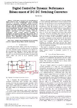
/
Abstract  In this paper an overv iew of recent advances in digital control of low to mediumpower Abstract  In this paper an overv iew of recent advances in digital control of low to mediumpower

Abstract In this paper an overv iew of recent advances in digital control of low to mediumpower - PDF document

conchita-marotz
conchita-marotz . @conchita-marotz
Follow
474 views
Uploaded On 2014-12-14

Abstract In this paper an overv iew of recent advances in digital control of low to mediumpower - PPT Presentation

Traditionally analog electronics methods have dominated in cont rolling such dcdc converters However with the steadily decreasing cost of ICs the feasibility of digitally controlled dcdc switching converters has increased significantly This paper ou ID: 23799

Traditionally analog electronics methods

Share:

Link:

Embed:

Download Presentation from below link

Download Pdf The PPT/PDF document "Abstract In this paper an overv iew of ..." is the property of its rightful owner. Permission is granted to download and print the materials on this web site for personal, non-commercial use only, and to display it on your personal computer provided you do not modify the materials and that you retain all copyright notices contained in the materials. By downloading content from our website, you accept the terms of this agreement.


Presentation Transcript

Yan-Fei Liu Abstractiew of recent advances in digital control of low- to medium-power dc-dc switching converters is presented. Traditionally, analog electronics methods have dominated in controlling such dc-dc converters. However, with the steadily decreasing cost of ICs, the feasibility of digitally controlled dc-dc switching converters has increased significantly. This paper outlines a sample of digital solutions for dc-dc switching converters to enhance the dynamic performance of dc-dc switching converters. Furthermore, latest research activities pertaining to applications for dynamic performance improvement, such as controller auto-tuning, capacitor charge balance control, are discussed. These applications demonstrate the significant advantages and potentials of digital control. — Digital control technologies, Dc-dc switching converter, Capacitor charge balance control, Auto-tuning NTRODUCTIONOver the past decade, digital control has emerged as a viable candidate for low- to medium-power dc-dc switching converters. With the steadily decreasing cost of digital ICs, the cost-prohibitive attribute of digital control technology has begun to fade. Therefore, over the past few years, Q1 Q2 Lo Co ESR Driver ic vo+- iL Io Vin Converter Digital Control Law ref[n] + Digital Load A/D Converter vo[n]]d[n] WCE 2011 Proceedings of the World Congress on Engineering 2011 Vol II WCE 2011, July 6 - 8, 2011, London, U.K. ISBN: 978-988-19251-4-5 ISSN: 2078-0958 (Print); ISSN: 2078-0966 (Online) Yan-Fei Liu, PhD, Professor, Department of Electrical and Compute r Engineering, Queen’s University, Kingston, Ontario, Canada, K7L 3N6.Email: yanfei.liu@queensu.ca (causing a 90° phase lag in the loop), the output voltage will oscillate at the resonant frequency of the converter. This frequency is measured and stored. This allows for the proper placement of the first zero of a PID compensator. The new PID controller is passed through a low-pass filter to force the desired phase margin at the desired crossover frequency. The second zero is then iteratively placed until the output oscillates at the crossover frequency. After the two zeroes are placed, the compensator gain is set by using the desired bandwidth, zero placement, and an asymptotic Bode plot estimation. The relay function is disabled after the tuning process is completed, allowing for normal loop operation. The advantage of the aforementioned method is that only the frequency of the output voltage oscillation is required to be measured; the amplitude is not required, allowing for more robust operation. vo- Buck Converter e[n] Vin + A/D ref +- Relay Gc(z) DPWM d[n] Freq. Measurement Tuning Algorithm Fig. 2 Nonlinear relay to induce LCOs On the other hand, the above-mentioned auto tuning algorithms [1] - [4] induce a relatively large voltage oscillation at the output of the converter for a short period of time in order to tune the controller. However, the auto tuning algorithm presented in [11] follows a different approach, as illustrated in Fig. 3A relatively low-bandwidth multi-input–multi-output (MIMO) controller continuously adjusts the controller’s coefficients in an attempt to minimize the . The system operates by continuously injecting a varying frequency square wave into the DPWM input signal . The DPWM input signal and the digital compensator output signal are passed though a bandpass filter (bandpass equal to the injected frequency) and measured by the digital stability monitor. The injected frequency is adjusted until the magnitude of the two measured filtered signals are equal (indicating the crossover frequency ). By comparing the zero-crossover points of the two signals , the phase margin the system can also be calculated. The measured crossover frequency and phase margin are subtracted from the desired crossover frequency and phase margin to produce crossover frequency and phase margin errors (c_errIt is noted that with auto-tuning technology, the control circuit design is significantly simplified and dynamic performance is guaranteed. vo+- Vin Converter Digital Control (z) S Digital fcVz DC/DC Converter Digital Stability Margin Monitor Load Vx Vy ++ c_ref -+ m_ref +-Fm Low BW MIMO Adaptive Controllerc_errm_err CoefficientsFig. 3 Auto tuning based on continuous phase margin measurement III. HARGE ALANCE ONTROL A major application of dc-dc Buck converter is for powering modern processors in the computing industry. Due to the increasing load step/slew value and the stringent requirements of the regulated output voltage, the bandwidth barrier of the conventional linear mode controller needs to be broken through. Although multiphase dc-dc buck converter with conventional controller solution is provided in the market, the incremental transferred cost on the output capacitors apparently limits the applicability of this solution for the future. Under such demands, many advanced control methods are proposed to minimize the concerns or modifications on the hardware design, but achieving optimal or suboptimal response, for example, V control, sliding mode control and capacitor charge balance control. Charge balance control (CBC, also known as time-optimal control) involves attempting to drive a converter to steady state in the theoretically minimum time and was introduced in [12] for load transient and [17] for input voltage transient. Charge balance controllers typically behave as a linear controller when the converter experiences following a transient event. For example, as illustrated in Fig. 4, for a buck converter undergoing a load step transient, it involves a single switching transition at a precise moment. Due to the complex derivation involved, initially, this is well-suited for digital control and has received considerable research attention [8] - [17] and [18] - [21]. The concept involves determining the capacitor current zero-crossover point to estimate the output voltage peak/valley point [19] at . Another key time point is to decide when the switching state of the main switch should be changed, as shown in Fig. 4, at . Finally, the linear mode of controller will take over the regulation task after 3. Fig. 4 CBC response under load step transient In [17], shown in Fig. 5, a new optimal two-switching cycle compensation algorithm is proposed to achieve optimal transient performance for DC-DC converters under an input voltage change. Using the principle of capacitor charge balance, the proposed algorithm predicts the optimized two-switching cycle duty cycle series to drive the output voltage back to the steady state when the input voltage changes. But the algorithm will lose capabilities for regulation ultrafast and large input voltage transient cases. The controller proposed in [14] employs a asynchronous ADC to capture the time point based on the voltage valley/peak and uses this information to calculate the optimal switching time instants/intervals, while in [15] and [16], the information is used to calculate the correspondingly mapped output voltage at which the controller should alter its output (ON/OFF) state. An advantage of the controller presented in [15] and [16] is that the inductor and capacitor values are not required; however, it is assumed that the ESR of the capacitor is negligible. If not, the capacitor and ESR values would be required in order to compensate the lead time caused by ESR. From practical design point of view, a current limiting scheme is also concerned in [20], while, fast dynamic response performance can be achieved with proper modifications on original CBC algorithm. A digital implementation of CBC concept is discussed in [19] based on its analog counterpart [18]. In [19], a current estimation algorithm is presented for predicting capacitor current zero-crossover at . And a double accumulator is employed using FPGA to emulate the double integrator in analog domain [18] and enhance the previous controller performance for AVP extension. With the help of double accumulator/integrator, the algorithm dependence on inductance can be removed, however, for AVP applications the capacitance is still required to be known accurately for determining in the algorithm. Fig. 5 Charge balance controller response to an input voltage transient The above nonlinear controllers can be extended to multiphase operation [21] and [22]. In [21], rather than minimum recovery time, it compromises the aim only at achieving the minimum voltage deviations. Further, a smooth controller transition is realized by inserting specified ON/OFF sequences right after the capacitor current undergoes zero-crossover, shown in Fig. 6. However, under a negative load step transient, the improvement is minor because the conventional linear mode compensator is still well-suited for regulating the low output ratio converters with sub-optimal voltage overshoot. In [22], a current mode digital CBC controller is presented for multiphase Buck converters, which takes advantage of peak current control on the phase inductors to achieve minimum recovery time. During transients shown in Fig. 7, new steady-state current information can be collected at the voltage valley/peak point and the digital peak current reference can be calculated and set based on CBC principles. However, both of the methods [21] and [22] are still limited for low ESR Buck converters and sensitive for passive components’ value. Also, the controllers will not work as well for example, if a negative load step occurs before the valley point resulted from a previous positive load step is approached. Fig. 6 Principle of operation of the “large-small” signal compensator during light-to-heavy with inserted control sequence Fig. 7The key waveforms of a single-phase power stage during a light-to heavy load transient. Top: output voltage; Bottom: the inductor current. It is demonstrated in [18] shown in Fig. 8 that for low-duty-cycle conversion applications (e.g., 12 ), the voltage overshoot caused by a step-down load current transient may be more than five times as large as the corresponding voltage undershoot caused by a positive current step of equal magnitude. This is illustrated in Fig. 8. Therefore, to adhere to voltage specifications, capacitor selection must be based on the larger voltage overshoot condition. Numerous topology modifications to Buck and synchronous Buck converters have been proposed to address the aforementioned problem. Ideally, the steady-state duty cycle would be close to 50% in order to achieve a symmetrical transient response to positive and negative load current changes. One solution is to use two synchronous Buck converters in series in order to increase the duty cycle of the second stage. For example, the first stage could convert the voltages 12 and the second stage could convert the voltages 5 Therefore, the second stage’s steady-state duty cycle would be increased from 12.5% to 30%, yielding a much more symmetric transient response. This allows the use of a smaller inductor for a fixed inductor current ripple value. This concept is studied extensively in [23] and [24]. Fig. 8 Asymmetrical transient response to positive and negative load Three obvious drawbacks of this method are an increase ical size, and a decrease in efficiency. However, it is argued in [24] that if a low-enough switching frequency was used in the first stage, then the overall efficiency would not suffer. Fig. 9 Peak current mode, constant off-time operation of the proposed controller in [25] In [25], a controlled auxiliary circuit (CAC) is presented to improve the transient response of a Buck converte, as shown in Fig. 9. It is well established that for converter applications with a large input/ output voltage ratio, voltage overshoots (due to step-down load transients) are much larger than corresponding voltage undershoots (due to step-up load transients). Therefore, the goal of the proposed method is to reduce the overshoot. The control method only activates the auxiliary circuit during step-down load transients and operates by rapidly transferring excess load current from the output inductor of a Buck converter to the converter’s input. The proposed method behaves as a controlled current source shown in Fig. 9 to remove a constant regulated current from the output of the Buck converter. The duration of activation of the auxiliary circuit is also regulated. The proposed circuit has the following advantages: 1) predictable behavior allowing for simplified design; 2) inherent over-current protection; 3) low peak current to average current ratio allowing for use of smaller components. In addition, the proposed auxiliary controller estimates the magnitude of the unloading transient and sets the auxiliary current proportional to the transient magnitude. This allows for greater design flexibility and increases the auxiliary circuit efficiency for unloading transients of lesser magnitude. In this paper, it is shown through analysis, simulation, and experimental results that a large reduction of voltage overshoot and output capacitor requirements can be realized through the addition of a small MOSFET, diode, and inductor. Capacitor charge balance contgenerated numerous digital controllers and subsequent analog designs [8] - [25]. The end result is a very fast reaction to transient events with minimal/reduced settling time. The main drawbacks of the existing CBC implementation methods are as follows: (1) precise information of converter parameter information such as and is required; nsing is needed to detect the voltage peal/valley; (3) complex computation is embedded in CBC algorithm formulas (i.e. division or square root) (4) the ESR of the output capacitor is assumed to be negligible. IV. ONCLUSIONSThis paper provided a brief review of the latest development of digital control technologies to improve the dynamic performance of DC-DC switching converters. It demonstrates that with auto-tuning and charge balance control technologies, the dynamic performance of DC-DC converters can be significantly improved. EFERENCESENCES Z. Zhao and A. Prodic, “Limit-cycle oscillations based auto-tuning system for digitally controlled DC–DC power supplies,” IEEE Trans. Power Electron., vol. 22, no. 6, pp. 2211–2222, Nov. 2007. W. Stefanutti, S. Saggini, E. Tedeschi, P. Mattavelli, and P. Tenti, “Simplified model reference tuning of PID regulators of digitally controlled DC–DC converters based on crossover frequency ectron. Spec. Conf. (PESC), 2007, pp. 785–791. M. Shirazi, R. Zane, D. Maksimovic, L. Corradini, and P. Mattavelli, “Autotuning techniques for digitally-controlled point-of-load converters with wide range of capacitive loads,” in Proc. IEEE Appl. Power Electron. Conf. (APEC), 2007, pp. 14–20. W. Stefanutti, P. Mattavelli, S. Saggini, and M. Ghioni, “Autotuning of digitally controlled DC–DC converters based on relay feedback,” IEEE Trans. Power Electron., vol. 22, no. 1, pp. 199–207, Jan. 2007. J. Morroni, R. Zane, and D. Maskimovic, “Design and implementation of an adaptive tuning system based on desired phase margin for digitally controlled DC–DC converters,” IEEE Trans. Power Electron., vol. 24, no. 2, pp. 559–564, Feb. 2009. M. Shirazi, R. Zane, D. Maksimovic, L. Corradini, and P. Mattavelli, “Autotuning techniques for digitally-controlled point-of-load converters with wide range of capacitive loads,” in Proc. IEEE Appl. Power Electron. Conf. (APEC), 2007, pp. 14–20. W. Stefanutti, P. Mattavelli, S. Saggini, and M. Ghioni, “Autotuning of digitally controlled DC–DC converters based on relay feedback,” IEEE Trans. Power Electron., vol. 22, no. 1, pp. 199–207, Jan. 2007. V. Yousefzadeh, A. Babazadeh, B. Ramachandran, E. Alarcon, L. Pao, and D. Maksimovic, “Proximate time-optimal digital control for synchronous buck DC–DC converters,” IEEE Trans. Power Electron., vol. 23, no. 4, pp. 2018–2026, Jul. 2008. A. Babazadeh and D. Maksimovic, “Hybrid digital adaptive control for synchronous buck DC–DC converters,” in Proc. IEEE Power Electron. Conf. (PESC), 2008, pp. 1263–1269. E. Meyer, Z. Zhang, and Y.-F. Liu, “An optimal control method for buck converters using a practical capacitor charge balance technique,” IEEE Trans. Power Electron., vol. 23, no. 4, pp. 1802–1812, Jul. 2008. A. Soto, A. de Castro, P. Alou, J. A. Cobos, J. Uceda, and A. Lotfi, “Analysis of the buck converter for scaling voltage of digital circuits,” IEEE Trans. Power Electron., vol. 22, no. 6, pp. 2432–2443, Nov. 2007. G. Feng, E. Meyer, and Y. F. Liu, “A new digital control algorithm to achieve optimal dynamic response performance in DC-to-DC converters,” IEEE Trans. Power Electron., vol. 22, no. 4, pp. 1489–1498, Jul. 2007. S. Effler, A. Kelly, M. Halton, T. Kruger, and K. Rinne, “Digital control law using a novel load current estimator principle for improved transient response,” in Proc. IEEE Power Electron. Spec. Conf. (PESC), 2008, pp. 4585–4589. Z. Zhao and A. Prodic, “Continuous-time digital controller for high frequency DC–DC converters,” IEEE Trans. Power Electron., vol. 23, no. 2, pp. 564–573, Mar. 2008. A. Costabeber, L. Corradini, P.Mattavelli, and S. Saggini, “Time optimal, parameters-insensitive digital controller for DC–DC buck ters,” in Proc. IEEE Power Electron. Spec. Conf., 2008, pp. 1243–1249. L. Corradini, A. Costabeber, P.Mattavelli, and S. Saggini, “Time optimal, parameters-insensitive digital controller for VRM ge positioning,” in Proc. IEEE Workshop Control Model. Power Electron. (COMPEL), 2008, pp. 1–8. G. Feng, E. Meyer, and Y.-F. Liu, “A digital two-switching-cycle compensation algorithm for input-voltage transients in DC–DC converters,” IEEE Trans. Power Electron., vol. 24, no. 1, pp. 181–191, Jan. 2009. E. Meyer, Z. Zhang, and Y.-F. Liu, “An optimal control method for buck converters using a practical capacitor charge balance technique,” IEEE Trans. Power Electron., vol. 23, no. 4, pp. 1802–1812, Jul. 2008. E. Meyer, Z. Zhang, Y.F. Liu, " Digital Charge Balance Controller with Low Gate Count to Improve the Transient Response of Buck Converters,” in Proc. IEEE Energy Conversion Congress & Expo (ECCE). 2009 2009 Amir Babazadeh, Luca Corradini, and Dragan Maksimovi, “Near Time-Optimal Transient Response in DC-DC Buck Converters Taking into Account the Inductor Current Limit,” in Proc. IEEE Energy Conversion Congress & Expo (ECCE). 2009 2009 Aleksandar Radi, Zdravko Luki, and Aleksandar Prodi and Robert de Nie, “Minimum Deviation Digital Controller IC for Single and Two Phase DC-DC Switch-Mode Power Supplies,” in Proc. IEEE Appl. Power Electron. Conf. (APEC), 2010 Jurgen Alico, Aleksandar Prodic, “Multiphase Optimal Response Mixed-Signal Current-Programmed Mode Controller,” in Proc. IEEE Appl. Power Electron. Conf. (APEC), 2010 P. Alou, J. A. Cobos, R. Prieto, O. Garcia, and J. Uceda, “A two stage voltage regulator module with fast transient response capability,” in Proc. IEEE Power Electron. Spec. Conf. (PESC), Jun. 2003, vol. 1, pp. 138–143. Y. Ren, M. Xu, K. Yao, Y. Meng, and F. C. Lee, “Two-stage approach for 12-V VR,” IEEE Trans. Power Electron., vol. 19, no. 6, pp. 1498–1506, Nov. 2004. E. Meyer, D. Wang, L. Jia and YF. Liu, "Digital Charge Balance it for Superior Unloading Transient Performance of Buck Converters,” in Proc. IEEE Appl. Power Electron. Conf. (APEC), 2010