/
Development of a lightweight, underactuated exoskeleton for load-carry Development of a lightweight, underactuated exoskeleton for load-carry

Development of a lightweight, underactuated exoskeleton for load-carry - PDF document

danika-pritchard
danika-pritchard . @danika-pritchard
Follow
407 views
Uploaded On 2016-06-03

Development of a lightweight, underactuated exoskeleton for load-carry - PPT Presentation

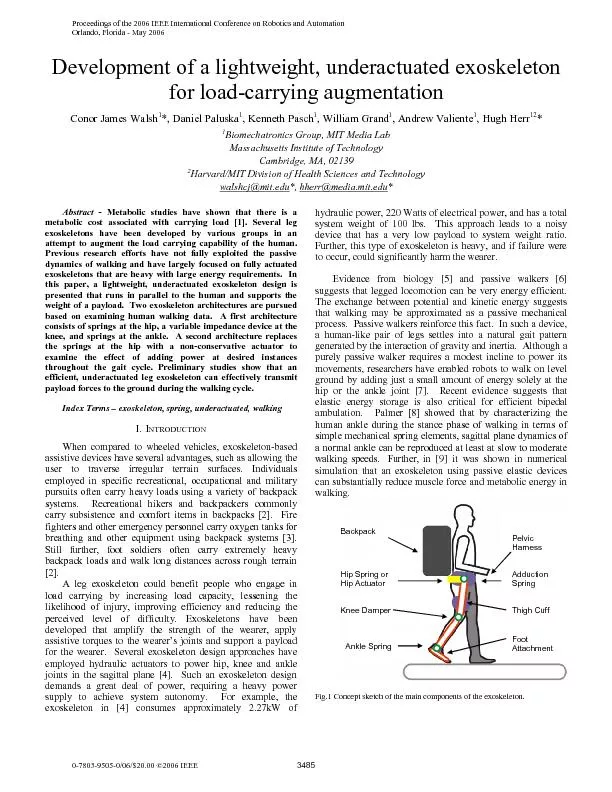
hherrmediamitedu Abstract Metabolic studies have shown that there is a Backpack nkle SpringKnee Damper Hip Spring or This paper examines biomechanical data from human walking and outlines th ID: 346865

hherr@media.mit.edu Abstract Metabolic studies

Share:

Link:

Embed:

Download Presentation from below link

Download Pdf The PPT/PDF document "Development of a lightweight, underactua..." is the property of its rightful owner. Permission is granted to download and print the materials on this web site for personal, non-commercial use only, and to display it on your personal computer provided you do not modify the materials and that you retain all copyright notices contained in the materials. By downloading content from our website, you accept the terms of this agreement.


Presentation Transcript

Development of a lightweight, underactuated exoskeleton for load-carrying augmentationConor James Walsh*, Daniel Paluska, Kenneth Pasch, William Grand, Andrew Valiente, Hugh HerrBiomechatronics Group, MIT Media Lab Massachusetts Institute of Technology Cambridge, MA, 02139 Harvard/MIT Division of Health Sciences and Technology walshcj@mit.edu *, hherr@media.mit.edu Abstract - Metabolic studies have shown that there is a Backpack nkle SpringKnee Damper Hip Spring or This paper examines biomechanical data from human walking and outlines the design of an alternative, more efficient exoskeleton that uses both passive and active elements. Two exoskeleton architectures are outlined. A first architecture consists of springs at the hip, a variable impedance device at the knee, and springs at the ankle. A second architecture replaces the springs at the hip with a non-conservative actuator to examine the effect of adding power at desired instances throughout the gait cycle. XOSKELETON ESIGNA.Methodology The exoskeleton was designed to provide a parallel load path to transfer the weight of the backpack directly to the ground. The exoskeleton had sufficient degrees of freedom to minimize kinematic constraints experienced by the wearer. The system was designed so that the distal mass of the exoskeleton was minimized. The requirement for hip actuation in the sagittal plane was to assist both the exoskeleton and human in walking. B.Degrees of Freedom The exoskeleton was implemented with three degrees of freedom at the hip, one at the knee, two at the ankle and one at the foot. The joint ranges of motion accommodated normal human walking. A cam mechanism was implemented at the hip joint to enable hip abduction/adduction. During abduction in the coronal plane, there was a length difference between the biological leg and the exoskeleton leg. This length difference resulted from dissimilar centers of rotation between the biological leg and the exoskeleton leg. This effect impeded normal walking motion and caused discomfort. A mechanism was designed to automatically adjust the exoskeleton leg length and project the center of rotation of the exoskeleton leg onto the biological hip center of rotation. Fig. 2 The roller is grounded to a hollow ½ steel shaft. When the leg abducts, the roller rides up the cam and the steel shaft slides up the bearing housing. The steel shaft is connected to the lower part of the exoskeleton leg so as the leg is abducted, the exoskeleton leg shortensC.Interface to the Human The exoskeleton interfaced to the human via shoulder straps, a waist belt, thigh cuffs, and a shoe connection. A compliant belt interfaced the lower torso to the backpack frame and the backpacks shoulder straps interfaced the upper torso. The physical connection between the exoskeleton and the human enabled the exoskeleton to passively track the humans leg motion. A standard military issued backpack, Alice Pack, was selected to carry the load. The exoskeleton was attached to the standard military backpack through a harness. The hip joints of the exoskeleton legs were mounted to the harness. There was sufficient clearance between the pelvic harness and the wearer to minimize disturbance to the wearers gait. D.Structure A parallel orthotic structure was the basic framework to transfer the load from the backpack to the ground. The main structural elements consisted of standard prosthetic aluminum tubing. This tubing was chosen since it is lightweight, rated for human use, and interfaces with standard prosthetic connectors and components. Fig. 3 Finite element modeling results from optimization of harness design along with final molded part. The harness connected rigidly to the backpack frame to transfer the load from the backpack to the exoskeleton. The pelvic harness was made from carbon fiber and the stiffness to weight ratio was optimized using finite element analysis. The structure consisted of a hollow core with 1/16 inch thickness of carbon fiber layer over it. A box was also incorporated into the harness for electronic part storage while at the same time offering an improved structural integrity.CTUATION ESIGN PECIFICATIONSA.Human Walking Biomechanics Human walking data were used in order to specify the design requirements for actuation at the exoskeleton joints. The power profiles for the hip, knee and ankle in the sagittal plane are plotted for a number of sets of gait data ([9], [10], [11], [12]). A conservative estimate of the weight of the exoskeleton and payload was chosen to be 60kg and the normative data were scaled to a 60kg person in order to estimate the torques and powers required at the joints of the exoskeleton. In estimating the torque and power requirements at the hip joint of the exoskeleton, the normative data were scaled to a 135kg person. This was due to the fact that the design goal was to have the actuator at the hip assist the exoskeleton (60kg) as well as the human (75kg). The human was assisted by means of a thigh cuff attachment between the human and exoskeleton thigh. The torque vs. angle plots use the data set from [11] which is for a walking speed of 0.8m/s. A number of assumptions were made in the application of the human biomechanical data to the design of the exoskeleton. The first is that the exoskeleton carries its own weight, power supply and payload. The second assumption is that joint torques and joint powers scale linearly with mass. This second assumptions seems reasonable given that increases in vertical ground reaction force have been found to be proportional to increases in the load being carried [13]. The third assumption is that the exoskeleton will not greatly affect the gait of the wearer. Changes in gait have been shown to increase the physiological energy expended during locomotion [14]. Fig. 4 illustrates the significant regions of positive and negative power during the gait cycle. Specifications for actuation components as well as control strategies are extracted from angle, torque and power data at the human hip, knee and ankle joints in the sagittal plane. Fig. 4 Summary of significant regions of positive and negative work in walking. The instances labeled here are referred to later in this paper when examining human walking data. 1)Hip During normal walking the human hip joint follows an approximate sinusoidal pattern with the thigh flexed forward on heel strike and then the hip moves through extension during stance as the body is pivoted over the stance leg in a pendulum-like motion. Positive power is required on heel-strike to raise the center of mass of the human over the stance leg. A peak negative hip torque of approximately 130Nm is experienced as the leg accepts load and the bodys center of mass is raised. A maximum positive torque of about 100Nm occurs during the swing phase as the hip muscles provide energy to swing the leg forward. This action is sometimes referred to as "pull off," and is the muscular system's second largest contribution of propulsive power during the gait cycle. The power profile at the hip as a function of gait cycle is shown in Fig 5. The hip joint is the preferred location for a non-conservative actuator as proximal mass is less expensive metabolically in walking than distal mass. 0 20 30 40 60 90 -150 -100 100 150 200 % Gait CycleHip Power (W) Linskell Kirtley (Young) Kirtley (Old) Bogert H1 H2 H3 Fig. 5 Hip joint power profile scaled for a 135kg person as a function of the gait cycle. H1 is a small region of positive power, not always present, which corresponds to concentric hip extensor activity during loading response, H2 is a region of negative power, corresponding to eccentric hip flexor activity during mid-stance and H3 is a region of positive power, corresponding to concentric activity in the hip flexors during pre-swing and initial swing.An actuator could assist in adding power in the H1 and H3 regions. From Fig. 5 it can also be seen that a spring placed at the hip joint could absorb the negative energy in H2 and release it during H3 to assist in swinging the leg forward. In Fig. 6 an approximate linear relationship can be seen between the hip torque and angle during the stance phase for slow walking (0.8m/s). The spring constant for such an “extension spring” was estimated as 115Nm/rad. As well as adding power throughout the gait cycle, a force-controllable actuator at the hip could be programmed to experiment with various impedance values. -10 5 15 20 35 -80 -60 -40 -20 40 60 Hip Angle (Deg)Hip Torque (Nm) Extension Flexion 115 Nm/rad Fig. 6 Hip angle plotted versus hip torque for a walking speed of 0.8m/s. 2)Knee In walking, the knee joint acts primarily as a variable-damper. Fig. 7 outlines the power of the knee as a function of gait cycle. It can be seen that the power is largely negative indicating that the knee absorbs power for the majority of the gait cycle. At heel strike there is a region of negative power followed by a period of positive power as the knee goes through stance flexion-extension. This is followed by a period of negligible joint power as the knee is passively extended. For a large part of the swing phase the leg has a pendulum like motion with the knee varying the damping to control the swing leg duration. 0 30 50 60 70 90 -120 -100 -80 -60 -40 -20 40 60 % Gait CycleKnee Power (W) Linskell Kirtley (Young) Kirtley (Old) Bogert K1 K2 K3 Fig. 7 Knee joint power profile scaled for a 60kg person as a function of gait cycle. K1 is a region of negative power, corresponding to eccentric knee extensor activity during the loading response, and K2 is a region of positive power, corresponding to concentric knee extensor activity during mid-stance. K3 is a region of negative power, corresponding to eccentric activity in the rectus femoris during pre-swing, and K4 is a region of negative power, corresponding to eccentric activity in the hamstrings during terminal swing. It can be seen in Fig. 7 that during flexion-extension during early stance, the knee behaves like a spring as there is a region of negative energy followed by a region of positive energy of similar size. Fig. 8 shows a plot of knee angle vs. torque and a linear relationship can be seem during the stance phase. For the remainder of the gait cycle, the knee acts like a variable-damper to control leg during the swing phase. -60 -50 -40 -30 -20 -10 0 -20 -15 -10 -5 0 5 Knee Angle (Deg)Knee Torque (Nm) Stance Flexion Stance Extension Swing Phase 136 Nm/rad Fig. 8 Plot of knee angle versus knee torque for the walking cycle. It can be seen that the knee behaves primarily as a variable damping device throughout the gait cycle. From the gait data it appears that the ideal actuator for the knee of the exoskeleton is a spring with a variable-damper. The spring would provide a resistive torque at the knee on heel strike as energy is absorbed and this energy is then released to aid in knee extension during stance. During the swing phase, the variable-damper would be engaged to control the swinging of the leg. It should be noted, for walking on a decline or down stairs, the variable-damper would be required during the stance phase to dissipate energy. For the initial implementation a variable-damper mechanism was used without the spring. The damper was able to provide the necessary resistive torque during stance but the negative energy was dissipated as heat. 3)Ankle During the mid and late stance phases of walking the ankle joint torque is negative for approximately 40% of the gait cycle as the ankle controls the forward movement of the center of mass. The maximum positive power input during the gait cycle occurs at toe off. At that time, the ankle torque is at its largest, approximately 90Nm. 0 40 50 60 70 100 -40 -20 40 60 80 100 120 140 160 % Gait CycleAnkle Power (W) Linskell Kirtley (Young) Kirtley (Old) Bogert A1 A2 Fig. 9 Ankle joint power profile scaled for a 60kg person as a function of gait cycle. A1 is a region of negative power, corresponding to eccentric plantar flexor activity at the ankle during mid-stance and terminal stance, and A2 is a region of positive power, corresponding to the concentric burst of propulsive plantar flexor activity during pre-swing. Fig. 10 shows the ankle torque plotted vs. angle for walking at 0.8m/s. A linear fit yields a spring constant for the ankle of 301Nm/rad for this walking speed. -10 -5 5 20 -90 -80 -70 -60 -50 -40 -30 -20 -10 Ankle Angle (Deg)Ankle Torque (Nm) Foot Flat DorsiFlexion PlantarFlexion Swing 301 Nm/rad Fig. 10 Plot of ankle angle versus ankle torque for the walking cycle. It can be seen that the ankle behaves like a spring at a walking speed of 0.8m/s. VI.PRELIMINARY ESULTS Initial walking experiments have been conducted with the exoskeleton loaded with a 75lb payload. The configurations with the passive extension springs and the non-conservative actuators at the hip were studied. It was discovered that the hip and knee angles followed similar trajectories to that of normal human gait kinematics, indicating that the exoskeleton does not negatively affect gait patterns in the sagittal plane. Further, it was determined that at least 90% of the weight of the payload and exoskeleton mass was transferred through the exoskeleton leg structure. Fig. 18 shows the load in the exoskeleton leg as a function of the gait cycle during a walking experiment. It can be seen that during the stance phase approximately 500N was transferred through the leg. At approximately 62% gait cycle, the load in the exoskeleton leg dropped to near zero as the leg entered the swing phase. 0 20 30 40 50 60 70 80 90 100 200 300 400 500 600 Load (N)Percent Gait CycleFig. 18 Load in the exoskeleton leg as a function of gait cycle. Heel strike is evident by a large increase in measured force level. During the swing phase it can be seen that there is minimal load in the exoskeleton leg. VII.ONCLUSIONS AND UTURE ORKIn this paper, a lightweight, underactuated exoskeleton is presented that runs in parallel to the human leg and transmits payload forces to the ground. Although primarily passive in design, the leg exoskeleton mechanism is shown to effectively transmit payload forces to the ground during walking.Through the analysis of fast walking and running biomechanics, we hope to design exoskeletons in the future that will allow for higher speed locomotory function. In addition to augmenting human strength and endurance, the advancement of leg exoskeletons can contribute to the science of bipedal walking and lead to a better understanding of locomotory biomechanics, energetics and control. VIII.CKNOWLEDGEMENTSThis research was done under Defense Advanced Research Projects Agency (DARPA) contract #NBCHC040122, ‘Leg Orthoses for Locomotory Endurance Amplification’. EFERENCES[1]T. M. Griffen, T. J. Roberts, R. Kram, “Metabolic cost of generating muscular force in human walking: insights from load carrying and speed experiments” Journal Applied Physiology 95: 172-183, 2003 [2]C. Fletcher, “The Complete Walker,” Alfred Knopf, New York, [3]V. Louhevaara, J. Smolander, T. Tuomi, O. Korhonen, J. Jaakkola, “Effects of an SCBA on breathing pattern, gas exchange, and heart rate during exercise,” J Occupational Mediceine, 27, 213-216, 1985 [4]A. Chu, H. Kazerooni, and A. Zoss, “On the Biomimetic Design of the Berkeley Lower Extremity Exoskeleton (BLEEX),” Proceedings of the IEEE International Conference on Robotics and Automation, Barcelona, Spain, pp. 4356 – 4363, 2005 [5]C. T. Farley and D.P Ferris, “Biomechanics of Walking and Running: from Center of Mass Movement to Muscle Action,” Exercise and Sport Sciences Reviews pp. 26:253-285, 1998 [6]T. McGeer, “Passive Dynamic Walking,” International Journal of Robotics, 1990 [7]M. Wisse, “Essentails of Dynamic Walking, Analysis and Design of two-legged robots,” PhD Thesis, Technical University of Delft, [8]M.L. Palmer, “Sagittal Plane Characterization of Normal Human Ankle Function Across a Range of Walking Gait Speeds,” MS Thesis, Massachusetts Institute of Technology, 2002 [9]A. J van den Bogert, “Exotendons for assistance of human locomotion,” Biomedical Engineering Online, 2:17, 2003 [10]C. Kirtley, CGA Normative Gait Database, Hong Kong Polytechnic University10 Young Adults. Available http://guardian.curtin.edu.au/cga/data/ [11]C. Kirtley, CGA Normative Gait Database, Hong Kong Polytechnic University10 Old Adults. Available http://guardian.curtin.edu.au/cga/data/ [12]J. Linskell, CGA Normative Gait Database, Limb Fitting Centre, Dundee, Scotland, Young Adult, Available http://guardian.curtin.edu.au/cga/data/ [13]R. Llyod and C. B. Cooke, “Kinetic changes associated with load carriage using two rucksack designs” Ergonomics43(9), 1331-1341, 2000 [14]T. A. McMahon, G. Valiant and E. C. Frederick, “Groucho Running,” Journal of Applied Physiology, 62(6) 2326-2337, 1987 [15]G. A. Pratt, M. M. Williamson, “Series Elastic Actuators,” IEEE RSJ International conference on Intelligent robots and systems,PA, 1995 [16]D. Robinson, “Design and analysis of series elasticity in closed-loop actuator force control,” PhD Thesis, Massachusetts Institute of Technology, 2000 [17]H. Herr and A. Wilkenfeld, “‘User-Adaptive Control of a Magnetorheological Prosthetic Knee,” Industrial Robot: An International Journal pp. 30: 42-55, 2003