/
Seismic Response of RC Frame Buildings with Soft First Storeys Proceed Seismic Response of RC Frame Buildings with Soft First Storeys Proceed

Seismic Response of RC Frame Buildings with Soft First Storeys Proceed - PDF document

danika-pritchard
danika-pritchard . @danika-pritchard
Follow
381 views
Uploaded On 2015-11-03

Seismic Response of RC Frame Buildings with Soft First Storeys Proceed - PPT Presentation

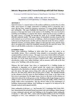
damage to the buildings with open basemee The recent Jabalpur earthquake of 22 May 1997 Jain et al 1997 also illustrated the handicap of Indian buildings with soft first storey This earst one in ID: 181244

damage the buildings with

Share:

Link:

Embed:

Download Presentation from below link

Download Pdf The PPT/PDF document "Seismic Response of RC Frame Buildings w..." is the property of its rightful owner. Permission is granted to download and print the materials on this web site for personal, non-commercial use only, and to display it on your personal computer provided you do not modify the materials and that you retain all copyright notices contained in the materials. By downloading content from our website, you accept the terms of this agreement.


Presentation Transcript

Seismic Response of RC Frame Buildings with Soft First Storeys Proceedings of the CBRI Golden Jubilee Conferenceon Natural Hazards in Urban Habitat, 1997, New DelhiDepartment of Civil Engin damage to the buildings with open basemee The recent Jabalpur earthquake of 22 May 1997 [Jain, et al, 1997] also illustrated the handicap of Indian buildings with soft first storey. This earst one in an urban neighborhood in India, provided an opportunity to assess the performance of engineered buildings in the country during ground shaking. The damage incurred by Himgiri and Ajanta apartments in the city of Jabalpur are very good examples of the inherent risk involved in the construction of buildings with soft first storey. Himgiri apartments is a RC frame building with open first storey on one side for parking, and brick infill walls on the other side. The infill portion of the building in the first storey is meant for shops or apartments. All the storeys on top have brick infill walls. The first storey columns in the parking area were badly damaged including spalling of concrete cover, snapping of lateral ties, buckling of longitudinal reinforcement bars and crushing of core concrete (Fig. 1). The columns on the other side had much lesser level of damage in them. There was only nominal damage in the upper storeys consisting of cracks in the filler walls. This is a clear case of columns damaged as a result of the “soft first storey”. The Ajanta apartments buildings are a set of almost identical four storey RC frame building located side-by-side. In each of these buildings, there are two apartments in each storey, excepting the first storey. One building has two apartments in the upper storeys, but only one apartment in the first storey. The open space on the other side is meant for parking, and hence has no infilled wall panels. Whereas, only nominal damages were reported in the building with two apartments the first storey, the first storey columns on the open side in the other building were very badly damaged. The damage consisted of buckling of Figure 1 :: Damage to columns in Himgiri apartment.In a two-storey (plus stilt storey) C-shaped RC frame building (Youth hostel building) in Jabalpur, the damage to the columns in the stilt storey consisted of severe X-type cracking due to cyclic lateral shear (Fig. 2). Here also, the two storeys above the stilt storey have brick infilled wall panels. This makes the upper storeys very stiff as compared to the storey at the stilt level. There was no damage to the columns in the storeys above. The “soft first storey” at the stilt level is clearly the primary reason for such a severe damage. In this paper, stiffness balancing is proposed between the first and second storey of a reinforced concrete moment-resisting frame building with open first storey and brick infills in the upper storeys. A simple example building is analyzed with different models. The stiffness effect on the first storey is demonstrated through the lateral displacement profile of the building, and through the bending moment and shear force in the columns stilt storey of Youth Hostel building.BUILDING STUDIEDThe plan layout of the reinforced concrete moment resisting frame building with open first storey and Un-reinforced brick infill walls in the upper storeys, chosen for this study is shown in Fig. 3. The building is deliberately kept symmetric in both orthogonal directions in plan to avoid toFurther, the columns are taken to be square to keep the discussion focused only on the soft first storey effect, without being distracted by the issues like orientation of columns. The building is considered to be located in seismic zone III and intended for residential use. The building is founded on medium strength soil through isolated footings (of size ) under the columns. When a central concrete service core is wide footing is taken to go all around under the wall in the core. To show the effect of soil flexibility, the modulus of surged reaction of the soil is taken as [Prakash, 1981]. Elastic moduli of concrete and masonry are and respectively, and their Poison’s ratio is . Performance factor (K) has been taken as (assuming ductile detailing). The unit weights of concrete and The weathering course on roof is taken as 2.25 kN/m. The live load on floor is taken as and that on roof as 0.75 kN/m. In the seismic weight calculations, only of the floor live load is considered. e example building considered in the study. Model I and II Model III Model IV Model V Model VI, VIII and IX Model VII Figure 4 :: Elevation of different building models considered in this study. Nine different models of the buildin :: Building has no walls in the first storey and one full brick infill masonry :: Building has no walls in the first storey and half brick infill masonry :: Building modeled bare frame. However, masses of the walls as in are included in the model. :: Building has one full infill masonry wall ( thick) in all storeys, :: Building has one full brick infill masonry walls (mm thick) in the upper storeys. Further, a central service core is introduced in the building, by providing thick brick masonry walls within the frame panels formed by the columns and beams in the central bay in the :: Building has one full brick infill masonry walls (mm thick) in the upper storeys. Again, a central service core is introduced in the building, by providing reinforced concrete walls ( thick in the first storey and mm in the upper storeys) within the frame panels formed by the columns and beams in the central service core in all :: Building has no walls in the first storey and one full brick infill masonry walls ( thick) in the upper storeys. However, the columns in the first storey are much stiffer () than those in the upper to reduce the stiffness irregularity between :: Building as in Model VI with soil flexibility introduced only under the concrete walls in the central core area; the columns are assumed to be :: Building as in Model VI with soil flexibility introduced under the concrete walls in the central core area as well as all the columns. ANALYSIS OF THE BUILDINGLinear elastic analysis is performed for the nine models of the building using analysis package [Habibullah, 1995]. The frame members are modeled with rigid end zones, the walls are modeled as panel elements, and the floors are modeled as diaphragms rigid in-plane. The soil flexibility is introduced as linear Winkler springs under the footing. When the central service core is used in models VIII and IX, the walls in the core are discretised finely into wide vertical strips to enable the modeling of a continuous soil support through linear Wrinkler springs. Two different analysis are performed on the models of the building considered in this study, namely the equivalent static analysis and the multi-modal dynamic analysis. These are briefly given in IS:1893-1984, wherein is the height and is the base dimension of the building in the considered direction of vibration. Thus, the natural periods for all the models in this method, is the same. The lateral load calculation and its distribution along the height is done as per IS:1893-1984. The seismic weight is calculated using of live load. Multi-Modal Dynamic AnalysisDynamic analysis of the building models is performed on . The lateral loads correspond to the seismic zone III and the damped response spectrum given in IS:18lues are calculated by by solving the eigen value problem of the model. Thus, the total earthquake load generated and its distribution along the height correspond to the mass and stiffness distribution as modeled by . Here, as in the equivalent static analysis, the seismic mass is calculated using full dead load plus RESULTS AND DISCUSSIONSThe displacements and forces from the equivalent static method are consistently than those from the multi-modal dynamic analysis method. For the building models at hand, the storey stiffness of the first and second storeys are shown in Table 1. The storey stiffness is defined as the magnitude of the force couple required at the floor levels adjoining the storey to produce a unwithin the storey, letting all the other floors to move freely. Table 1 :: Storey stiffness of first and seco Building Model Open First Storey:: 220mm thick walls in upper storeys 230 3448 227 5263 Open First Storey:: 110mm thick walls in upper storeys 225 2083 220 3030 Bare Frame 185 365 166 291 Brick Infilled Completely 2273 3571 3571 5263 Open First Storey 474 3333 694 5000 Open First Storey 2346 4349 4167 7143 Open First Storey with Stiffer Columns 2941 3846 2778 5556 Open First Storey + Flexible Soil under Core only 300 3125 308 4546 Open First Storey + Flexible Soil 205 1613 220 2857 The stiffness irregularity in building models with soft first storey is evident from the fact that the stiffness of the first storey for model I, II, is about and respectively. Of the second storey stiffness. Models and represent the actual buildings. It is seen that the reduction of the wall thickness in the upper storeys and addition of the brick service core reduces only marginally the stiffness irregularity. The stiffness of the first storey in model (bare frame) is about of that of the second storey. However, this does not imply that the building does not have stiffness irregularity. In fact, the bare frame idealization of the building, considering only the mass of the infill brick walls, is a grossly incorrect model for the building considered in this study. The use of RC service core (model ) or stiffer columns (model ) in the first storey reduces the stiffness irregularity. The first storey stiffness in these models are more than of the second storey stiffness. For model , this value is larger () in the transverse direction than in the longitudinal direction (). This effect is also observed in other models having fully open first storey. It is interesting to note that the percentage stiffness values for model (brick infilled completely) and model are very close. The introduction of foundation flexibility under the concrete service core (model ) drastically increases the stiffness irregularity; first and analytical () natural periods of the building models are shown in Table 2. It is seen that the analytical natural periods do not tally with the natural periods obtained from the empirical expression of the code. The bare frame idealization in leads to a severe overestimation of the natural period compared to the (actual) open first storey building in model I. This leads to an underestimation of the design lateral force in model Table 2 :: Codal and analytical fundamental natural periods of different building Fundamental Natural Period 0.42 0.43 0.27 0.42 0.42 0.38 0.27 0.38 0.42 0.64 0.27 0.71 0.42 0.18 0.27 0.15 0.42 0.31 0.27 0.26 0.42 0.18 0.27 0.13 0.42 0.16 0.27 0.15 0.42 0.38 0.27 0.37 0.42 0.5 0.27 0.44 The lateral displacement profiles of the various models for the two different analysis performed in this study are shown in Fig. 5. In these figures, the abrupt changes in the slope of the profile indicate the stiffness irregularity. All displacement profiles corresponding to models having stiffness irregularity (I, II, V, VIII and ) have a sudden change of slope at first floor level. However, the other models III, IV, VI, show smooth displacement profiles. The displacements at first floor level are shown in Table 3. The inter-storey drift demand is largest in the first storey for all the models with soft ground storey. This impdemand on the columns in the first storey, for these models, is the largest. For the models which do not have stiffness irregularity the first floor displacement is small, approximately of the corresponding values in model . Thus, the drift ductility demand in the first storey the storey stiffness at least equal to (a) Figure 5: Lateral Displacement Profile by (a) Equivalent Static Analysis and (b) Multi-Modal Dynamic Analysis.The maximum bending and maximum shear forces in the columns in the first and the upper storeys are shown in Table 3; the bending moment and shear force (strength) demands are severely higher for first storey columns, in case of the soft first storey buildings. The introduction of walls in the first storey (model ) reduces the force in the first storey columns. As the force is distributed in proportion to the stiffness of the members, the force in the columns of the upper storeys, for all the models (except ), are significantly reduced due to the presence of brick walls. These forces (bending moment and shear force) are about of the corresponding values in the first storey columns. The use of brick service core is not very effective in reducing the strength demand on the first storey columns. However, the force values are around of the values in case of model . When concrete service core is used, the demand on the columns is significantly reduced (by a factor of about ). Interestingly, the drift demands on the first storey columns in case of model (completely infilled) and model (stiffer columns in first storey) are very close. This is true for strength demands also. Thus, it is possible to replace all the brick infills in the first storey with a single concrete core as far as the drift and strength demands on the first storey columns are concerned. Model (stiffer columns in first storey) results in first storey drift demands similar to that of model (completely infilled), but the strength demand on the first storey columns is very large; the strength demands in model of those in model Table 3 :: Displacement at first floor, maximum forces in first storey columns and average of the maximum forces in the columns of the storeys above for Displacement Maximum Moment (kNm)Maximum Shear (kN) at First Floor Equivalent Static Analysis 2.7 3.1 56.4 6.2 62.7 4.8 27.2 4.5 30.1 3.6 2.2 2.5 45.0 8.2 50.4 7.2 21.6 6.0 24.1 5.8 3.9 5.2 70.4 43.9 85.3 49.9 31.7 32.3 36.5 37.5 0.3 0.2 6.6 6.2 4.5 6.4 3.1 4.4 2.1 3.5 1.4 1.0 27.5 5.4 20.8 4.7 13.1 3.7 10.0 3.3 0.3 0.2 6.7 8.2 3.9 6.3 3.4 5.8 1.9 4.3 0.2 0.3 76.2 5.3 84.1 3.8 32.9 3.9 34.9 2.9 2.1 2.3 46.8 15.6 45.8 6.8 23.3 10.7 22.0 4.8 3.3 3.2 70.6 31.1 71.1 34.6 34.5 21.8 35.4 24.7 Multi-Modal Dynamic Analysis 2.3 2.4 48.1 4.5 48.7 4.7 23.2 3.4 23.5 3.2 1.9 1.9 38.0 6.0 44.0 7.1 18.3 4.5 18.8 4.8 2.5 2.6 45.2 23.4 39.1 22.4 20.4 17.5 19.0 17.6 0.3 0.2 5.8 4.7 3.6 3.9 2.8 3.4 1.8 2.9 1.3 0.9 25.9 4.0 17.7 3.3 12.4 2.8 8.4 2.3 0.3 0.1 6.1 7.1 3.1 5.1 3.1 5.0 1.6 3.5 0.2 0.2 65.5 4.0 67.8 2.9 28.4 2.9 28.2 2.3 1.8 1.8 41.9 14.1 37.2 5.1 21.1 9.7 17.9 3.6 2.6 2.4 57.5 28.6 55.2 30.0 28.5 20.0 27.8 21.4 From the above discussion, it is seen that the concrete service core is as effective as providing infilled panels in the first storey of the building. However, the foundation flexibility, if present, can substantially impair its effectiveness. In models and where the flexibility of the soil is also modeled, both first storey drift and the forces in the columns increase. For model , these are about higher than those in model Thus, it is important to incorporate the soil flexibility, if present, in the modeling of the buildings, failing which the drift and strength demands in the first storey columns can be under-estimated, resulting in an incorrect design of the building. CONCLUSIONSRC frame buildings with open first storeys are known to perform poorly during in strong earthquake shaking. In this paper, the seismic vulnerability of buildings with soft first storey is shown through an example building. The drifdemands in the first storey columns are very large for buildings with soft ground very easy to provide such capacities in the columns of the first storey. Thus, it is clear that such buildings will exhibit poor performshaking. This hazardous feature of Indian RC frame buildings needs to be recognized immediately, and necessary measures taken to improve the performance of the The open first storey is an important functional requirement of almost all the urban multi-storey buildings, and hence, cannot be eliminated. Alternative measures need to be adopted for this specific situation. The under-lying principle of any solution to this problem is in (a) increasing the stiffnesses of the first storey such that the first storey is at least as stiff as the second storey, , soft first storeys are to be avoided, and (b) providing adequate lateral strength in the first storey. The possible schemes to achieve the above are (i) provision of stiffer columns in the first storey, and (ii) provision of a concrete service core in the building. The former is effective only in reducing the lateral drift demand on the first storey columns. However the latter is effective in reducing the drift as well as the strength demands on the first storey columns. The soil flexibility needs to be examined carefully before finalizing the analytical model of a building. Flexible soil conditions may require alternate solutions than those described in this paper, to reduce seismic drift and strength demands on the columns in the first storey. ACKNOWLEDGMENTSment of Science and Technology (DST), New Delhi, for conducting this post-Jabalpur earthquake study, is gratefully REFERENCESAIJ, 1995, “Preliminary Reconnaissance Report of the 1995 Hyogoken-Nanbu EQEI, 1994, “The January 17, 1994 Northridge, California Earthquake - An EQE EQE Internationalrthquake January 17, 1994 - Preliminary Reconnaissance Report,” Report No.94-01, Earthquake Engineering Research InstituteRepair and Strengthening of Buildings - Indian Standard Guidelines“Some Observations on Engineering Aspects of the Jabalpur Earthquake of 22 May 1997,” EERI Special Earthquake Report, EERI Newsletter IS:1893 Provisions on ETABS - Three Dimensional Analysis of Building Systems, , Computers and Structures, Inc., Berkeley, CA, USA.