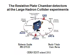
at the Large Hadron Collider experiments Roberto Guida Paolo Vitulo PHDTDI Univ Pavia CERN EDIT school 2011 1949 Keuffel ID: 801275
Download The PPT/PDF document "The Resistive Plate Chamber detectors" is the property of its rightful owner. Permission is granted to download and print the materials on this web site for personal, non-commercial use only, and to display it on your personal computer provided you do not modify the materials and that you retain all copyright notices contained in the materials. By downloading content from our website, you accept the terms of this agreement.
Slide1
The Resistive Plate Chamber detectors at the Large Hadron Collider experiments
Roberto
Guida Paolo Vitulo
PH-DT-DI Univ. Pavia
CERN
EDIT school 2011
Slide21949:
Keuffel
first
Parallel Plate Chamber 1955: Conversi used the “PPC idea” in the construction of the flash chambers 1980: Pestov Planar Spark chambers – one electrode is resistive – the discharge is localised 1982: Santonico development of the Resistive Plate Chamber – both electrode are resistive RPC applications: ‘85: Nadir (n-n\bar oscillation) – 120 m2 (Triga Mark II – Pavia) ‘90: Fenice (J/ n-n\bar) – 300 m2 (Adone – Frascati)‘90: WA92 – 72 m2 (CERN SPS)‘90: E771– 60 m2; E831 – 60 m2 (Fermilab)1992: development of RPC detector suitable to work with high particle rate towards application at LHC 1994-1996: L3 – 300 m2 (CERN-LEP)1996-2002: BaBar – 2000 m2 (SLAC)
Some history
Slide3Identikit of RPC detectors for LHC
Basic parameter for a detector design:
Gap width
Single gap/double gap/multi gap design Gas mixture Gas flow distribution Bakelite bulk resistivity Linseed oil electrode coatinges
Slide4The RPC detector
Gap
width 2 mm:
Good compromise between good efficiency, time resolution and rate capability More gaps:Increase time resolution and efficiency Double gap design:Best ratio induced/drift charge, therefore best signal/charge ratio Freon based mixture:Higher efficiency (at the same gas gain) and lower streamer probability Bakelite bulk resistivity = 1-6 1010 W cm:Good compromise between high rate capability and low current and noise Linseed oil treatment:Lower current and noise rate. No ageing effect observed
Slide5Why the RPC?
Drift chambers (cylindrical geometry) have an important limitation:
Primary electrons have to drift close to the wire before the charge multiplication starts
limit in the time resolution 0.1s Not suitable for trigger at LHC+ In a parallel plate geometry the charge multiplication starts immediately (all the gas volume is active).+ much better time resolution ( 1 ns)+ less expensive ( 100 €/m2)However:-Smaller active volumeElectrical discharge may start more easilyRelatively expensive gas mixtureQuite sensitive to environmental conditions (T and RH)
Slide6Lab. activity:
Switch on the RPCs
HV scan
Pulse height Pulse charge
Slide7Avalanche signal
Streamer signal
Towards a new operation regime
Originally RPC were operated in Streamer mode:Ar-based mixtureHigher signal (100 pC) but also high current in the detectorVoltage drop at high particle rate loss of efficiency poor rate capability (< 100 Hz/cm2) Operation with high particle rate possible in Avalanche mode:Freon-based mixturelower signal ( pC) but also lower current in the detectorLess important high voltage drop at high particle rate good rate capability ( 1 kHz/cm2)R. Santonico et al.ATLAS Muon TDR
Slide8Ionizing particles passing through the gas are producing primary ionization
Primary electrons accelerated in the electric field will start to produce further ionization
n
total: total number e-/IonE: total energy lossWi: <energy loss>/(total number e-/Ion)Working principle
Slide9Gain
Primary e
-
Charge multiplication = first Townsend coefficient= attachment coefficient = - = effective Townsend coefficientx 20 M 108 Reather breakdown limit
Slide10Time constant for charge development is related to drift velocity and multiplication
Time constant for recharge the elementary cell is related to the RC
discharge << recharge Are the most important improvement with respect to previous generationsSince recharge >> discharge the arrival of the electrons on the anode is reducing the electric field and therefore the discharge will be locally extinguished.the electrode are like insulator after the first charge development Self-extinguish mechanismHV
discharge
=
1/
v
d
~ 10 ns
recharge
=
~ 10 ms
Why resistive electrodes?
Slide11The RPC detector: gap width
The gap width is affecting both
time performance charge distribution
Narrow gap better time resolution, but “more critical” charge spectrum (R seems to be the driving parameter) reduce number of primary electrons R = l/R > 1R < 1 cluster density (primary clusters)g =const = 18M. Abbrescia et al. NIMA 471 55-59
Slide12The RPC detector: single vs double gap
The double gap layout:
allow to operate at lower
(i.e. lower high voltage)best ration qind/qtot (single 0.7; double 1.4; 3 gaps 0.8)Better charge distributionTwice expensive per unit of active area
Slide13Formation of the induced signal
Equivalent circuit of double RPC near the discharge region:
Ratio between total charge and induced charge on the strips:
Slide14The RPC detector: gas mixture
Key parameters:
cluster density (primary clusters) – only gas dependent
first Townsend coefficient (charge multiplication) – gas, HV dependent attachment coefficient – gas (electronegative and/or quencher), pressure dependent effective Townsend coefficient = - High gas: high efficiency and low streamer probability at the same !i.e. for avalanche regime: better Freon ( = 5.5 mm-1) than Ar ( = 2.5 mm-1)Voltage increasing
Slide15The RPC detector: gas mixture
Key parameters:
Moreover quencher (iC
4H10) and electronegative (SF6) gases will help in containing the charge development and reducing the streamer probability Charge distribution:avalanche streamerFraction of streamer vs High voltage:M. Abbrescia et al. NIMA 508 142-146R. Santonico Scientifica Acta Pavia
Slide16The RPC detector: gas mixture
Key parameters:
Large are giving also a better charge distribution (constant )
≤ 4 mm-1 spectrum monotonically decreasingCharge spectrum vs Streamer probabilityM. Abbrescia et al. NIMA 431 413-427
Slide17The RPC detector: gas flow distribution
Experience says that the gas flow has to be at least
0.3 vol / h even without radiation
Is the gas distribution inside the gap the origin of this limit?Is there a space for future improvements? Some preliminary results coming from a finite element simulation: Waldemar MaciochaAntonio RomanazziThe velocity field shows areas in which the gas is hardly movingThanks toGas velocity (m/s)inlets
Slide18RPC detector: bakelite resistivity
The detector rate capability is strongly dependent on the bakelite resistivity.
At high particle rate (r) the current through the detector can become high enough to produce an important voltage drop (V
d) across the electrode:s: electrode thickness<Qe>: average pulse charge: bakelite resistivity In order not to lose efficiency Vd < 10 V Therefore r ~ 1010 W cm The time constant of an elementary cell is lower at lower resistivity:the cell is recovering faster (it is quicker ready again) after a discharge took place inside it.
Slide19RPC detector:
linseed oil surface treatment
RPC electrodes are usually treated with linseed oil:
better quality of the internal electrode surfaceit acts as a quencher for UV photonsbetter detector performance …but…More time needed during constructionAgeing problems? (Not observed)What is the linseed oil:Drying oil (consists basically of triglycerides)Drying is related to C=C group in fatty acidCross-linking (polymerization) in presence of air (O2 play important role) due to C=C
Slide20RPC detector:
linseed oil surface treatment
Few SEM photos (S.Ilie, C.Petitjean EST/SM-CP EDMS 344297):
Defect on Bakelite surface possibly covered with linseed oilThickness of the layer: ~ 5 mThe linseed oil layer is damaged by a surface outgassing
Slide21RPC detector:
linseed oil surface treatment
Effect on UV photons hitting the electrode internal surface:
Linseed oil absorbance8 eV5.6 eVUV sensitivity for coated and non coated BakeliteC.Lu NIMA 602 761-765P.Vitulo NIMA 394 13-20
Slide22RPC detector:
linseed oil surface treatment
Chamber Performance:
With linseed oil coated electrodesLower current (1/10) Lower noise rate (1/10) M. Abbrescia et al. NIMA 394 13-20
Slide23RPCs for LHC experiments
Why RPCs for application in LHC experiments need a particular “care”?
Huge (
5000 m2 of sensitive area) and very expensive (6 106 CHF) systems (for comparison BaBar was about 2000 m2)Very long period of operation expected (at least 10 years)Very high level of background radiation expected Integrated charge never reached before: 50 mC/cm2 for ALICE and CMS 500 mC/cm2 in ATLASLarge detector volume basically impossible to operate the gas system in open mode closed loop operation gas mixture quality
Slide24RPCs for LHC experiments
Where are the RPCs systems at LHC?
ATLAS experiment:
- Active surface 4000 m2 - 94.7% C2H2F4; 5% iC4H10; 0.3 % SF6- Gas Volume 16 m3 - 40% Rel.Humidity- Expected rate ~ 10 Hz/cm2 - Closed loop operationCMS experiment:
Slide25Closed loop gas circulation
Large detector volume (
~
16 m3 in ATLAS and CMS) use of a relatively expensive gas mixture closed-loop circulation system unavoidable. Nowadays with 5-10 % of fresh gas replenishing rate cost is 700 €/dayBut….Several extra-components appear in the return gas of irradiated RPCsDetector performances can be affected if impurities are not properly removed Purifiers:
Slide26Gas analysis results: chromatography
Many extra components identified in the return mixture from detector
Operated with open mode gas system
Under high gamma radiation Concentration of the order of 10 ppmMainly hydrocarbonsother Freon
Slide27With respect to reference bakelite surface:
High fluorine concentrationNa signal appeared
N signal disappeared
Linseed oil and melamine layer etched:Na is used as a catalyser for phenolic resin (bulk)Normal surface layer (made on melamine resin) contain N Bakelite SEM resultsWe analyzed few bakelite samples from an RPC with relatively high current. The visual inspection of the surface shows at least two different kinds of surface defects:Reference bakelite
Slide28Operation of RPC detectors
The operation of a large area detector is never simple.
“Second order” problems may come from anywhere and anytime.
Few example:Gas quality is a crucial issue for all gaseous detectors (therefore also for RPC)Environmental conditions (like temperature and relative humidity) are affecting the detector performances (complex network of sensors is needed in order to understand behaviours)Gas leaks in the detector (unfortunately is a weak point) In the following, for time reason, I will discuss only an example concerning the gas quality
Slide29RPC detectors at LHC: some data
A
CMS event with
muon track reconstructedLab. activity: Switch on the RPCs
Slide30Lab. activity:
Pulse charge spectra
Avalanche vs. Streamer
SignalsTime behaviorChargeNoise charge spectra
Slide310.05% SF6
0% SF6
0.2% SF6
Slide320% SF6
0,05 % SF6
0,2 % SF6