/
2015 Amphenol Thermometrics Inc 2015 Amphenol Thermometrics Inc

2015 Amphenol Thermometrics Inc - PDF document

elyana
elyana . @elyana
Follow
347 views
Uploaded On 2021-08-17

2015 Amphenol Thermometrics Inc - PPT Presentation

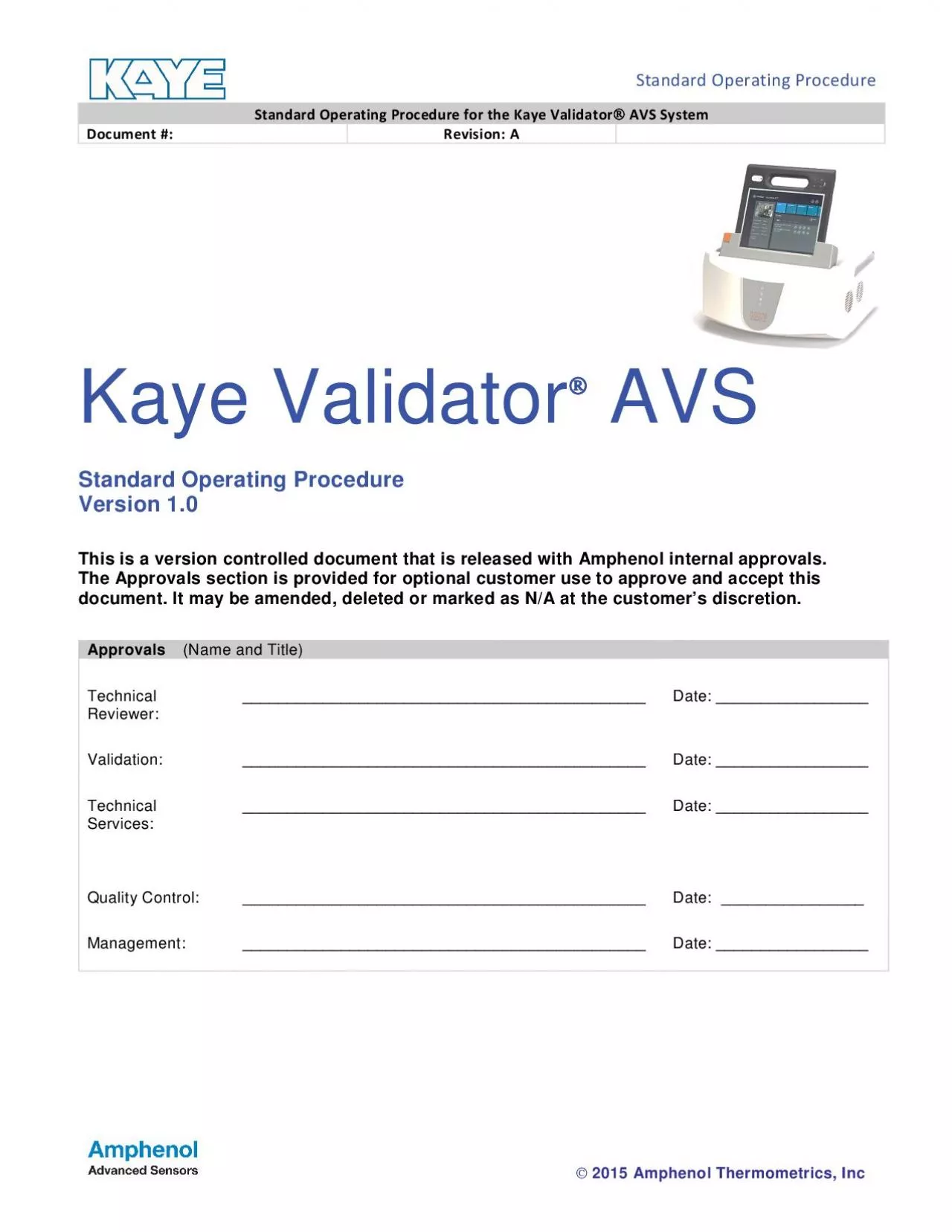
nrnnnrnnnnnnnKaye Validator AVS Standard Operating Procedure Version 10 This is a version controlled document that is released with Amphenol internal approvals The Approvals section is provided for o ID: 865574

validator kaye calibration avs kaye validator avs calibration sensor sensors temperature qualification setup click select reference system file reports

Share:

Link:

Embed:

Download Presentation from below link

Download Pdf The PPT/PDF document "2015 Amphenol Thermometrics Inc" is the property of its rightful owner. Permission is granted to download and print the materials on this web site for personal, non-commercial use only, and to display it on your personal computer provided you do not modify the materials and that you retain all copyright notices contained in the materials. By downloading content from our website, you accept the terms of this agreement.


Presentation Transcript

1  \n  \r\n\n 
 \n  \r\n\n  \n  \r\n\n\n\n ÒÒ\n \n\n    2015 Amphenol Thermometrics, Inc  Kaye ValidatorÒÒ AVS Standard Operating Procedure Version 1.0 This is a version controlled document that is released with Amphenol internal approvals. The Approvals section is provided for optional customer use to approve and accept this document. It may be amended, deleted or marked as N/A at the customer’s discretion. Approvals (Name and Title) Technical Reviewer: _____________________________________________ Date: _________________ Validation: _____________________________________________ Date: _________________ Technical Services: _____________________________________________ Date: _________________ Quality Control: _____________________________________________ Date: ________________ Management: _____________________________________________ Date: _________________  \n  \r\n\n  \n  \r\n\n\n\n ÒÒ\n \n\n  \r !"#  2015 Amphenol Thermometrics, Inc  TABLE OF CONTENTS 1.PURPOSE ..........................................................................................................................................................32.SCOPE ...............................................................................................................................................................33.SAFETY .............................................................................................................................................................34.EQUIPMENT ......................................................................................................................................................35.REFERENCE ......................................................................................................................................................46.SYSTEM DESCRIPTION .....................................................................................................................................46.1.Kaye Validator AVS ......................................................

2 ........................................
...................................................................................46.2.Kaye Validator Software Version 1.28 ..............................................................................................................46.3.Sensor Input Modules (SIMs) ...........................................................................................................................46.4.Temperature Reference ...................................................................................................................................6.5.IRTD ...............................................................................................................................................................57.SYSTEM ACCESS ..............................................................................................................................................58.PROCEDURES ...................................................................................................................................................68.1.Wiring SIMs .....................................................................................................................................................68.2.Starting the Kaye Validator AVS Software ........................................................................................................78.3.Creating/Modifying a Setup ..............................................................................................................................8.4.Connecting the System ....................................................................................................................................98.5.Checking Hardware and Communications Connections.....................................................................................98.6.Operation ...................................................................................................................................................... 108.6.1.Sensor Calibration ................................................................................................................................ 108.6.2.Qualification Study ...................................................................................................

3 ............................. 118.6.3.Ca
............................. 118.6.3.Calibration Verification .......................................................................................................................... 12Generating Reports ................................................................................................................................................. 138.6.4.Generating Setup Reports ..................................................................................................................... 138.6.5.Generating Calibration Reports ............................................................................................................. 138.6.6.Generating Qualification Reports ........................................................................................................... 138.6.7.Generating Verification Reports ............................................................................................................. 158.7.Using the Kaye Validator Audit Trail ............................................................................................................... 158.7.1.Accessing the Audit Trail ....................................................................................................................... 158.7.2.Filtering and Printing the Audit Trail ....................................................................................................... 15  \n  \r\n\n  \n  \r\n\n\n\n ÒÒ\n \n\n  \r $"#  2015 Amphenol Thermometrics, Inc  1. PURPOSE To provide an operational procedure that describes the setup and use of the Kaye ValidatorAVS system. 2. SCOPE This standard operating procedure provides safety information, a list of required equipment, a description of the system, and instructions for connecting inputs to Sensor Input Modules (SIMs), starting the Kaye Validator AVS software, creating/modifying a setup file, connecting the system, calibrating sensors, running a qualification study, verifying sensor calibration, generating reports, and accessing the Kaye Validator AVS audit trail. This procedure assumes that the Kaye Validator AVS software version 1.0 ha

4 s been installed and the System Administ
s been installed and the System Administrator has created user accounts. See Kaye Validator AVS User’s Guide for more information. 3. SAFETY The following safety precautions shall be observed when working around steam, high temperature ovens, and autoclaves during qualification studies: Ensure all electrical plugs are plugged in completely. Ensure all extension cords are correctly routed from wall receptacles. Do not route cords across active hallways or walkways without taping to floor or routing overhead. Know location of emergency shut-off switches, if applicable. Remove any heat-sensitive instruments from the system that could be damaged during steaming. Ensure all gaskets are in place before steaming. Ensure all doors, hatches, and so forth are closed before starting qualification studies. Steaming temperatures may exceed 121°C. Do not touch any exposed surfaces while steaming. Ensure equipment being tested is cool before attempting to remove thermocouples. 4. EQUIPMENT A complete Kaye validation system includes: The Kaye Validator AVS instrument with Version 0.0.1.42 firmware. The Kaye Validator AVS software version 1.28 for Microsoft Windows Embedded 8.1 Professional (64-bit). A printer that supports both portrait and landscape page orientation. Up to four Kaye Sensor Input Modules (SIMs). A Kaye high temperature reference (HTR 400), low temperature reference (LTR-90, LTR –25/140 or LTR –40/140), or a cold temperature reference (CTR –40 or CTR –80) for sensor calibration and verification. A Kaye Intelligent RTD Probe (IRTD). Premium grade thermocouples. Additional temperature and non-temperature sensors for qualification studies (optional).  \n  \r\n\n  \n  \r\n\n\n\n ÒÒ\n \n\n  \r %"#  2015 Amphenol Thermometrics, Inc  5. REFERENCE Kaye Validator AVS User’s Guide, Document M5100 6. SYSTEM DESCRIPTION This section describes the Kaye Validator AVS system and associated equipment. 6.1. Kaye Validator AVS Self-contained thermal validation device with high accuracy sensor measurement hardware and secure data recording capability. Standalone functionality when calibrating senso

5 rs, running qualification studies, and v
rs, running qualification studies, and verifying sensor calibration. Accepts up to 48 inputs in any combination of thermocouple, voltage, and current inputs. System accuracy after calibration, taking into account all sources of error including the Kaye Validator and calibration and reference standards: 0.28°C at 121°C 0.38°C at 250°C 4 GB of internal memory to maintain qualification data during a study. Qualification data resides in internal memory until system is powered down or a new setup is loaded. Lithium ion backup battery to provide short-term power in case of AC power loss. A fully charged battery will provide approximately 120 minutes to perform an orderly shutdown of the system. 6.2. Kaye Validator Software Version 1.28 Create user accounts and assign user IDs, passwords and permission levels. Create validation study setups that can be run standalone or Console-controlled. When calibrating sensors and running qualification studies from the Console, the Kaye Validator AVS software features expanded tools for viewing and displaying data. Generate reports from secure data files that contain original calibration and qualification data recorded during the study. Access the Kaye Validator AVS audit trail, which provides a complete listing of events that affect the integrity of the Kaye Validator AVS software and the Kaye Validator AVS instrument. Fly out help guide in software operation. 6.3. Sensor Input Modules (SIMs) Sensor input module to which thermocouples or other measuring devices are connected. Each SIM has 12 sensor connections. Each SIM has a memory chip to store calibration offsets, SIM serial number, slot location, and the serial number of the Kaye Validator AVS measurement board on which calibration is performed. SIMs can be wired by the user or purchased pre-wired.  \n  \r\n\n  \n  \r\n\n\n\n ÒÒ\n \n\n  \r &"#  2015 Amphenol Thermometrics, Inc  6.4. Temperature Reference Temperature references provide the stable temperature required for sensor calibration. Amphenol Advanced Sensors has five temperature reference models available. They are designed to provide diff

6 erent temperature ranges and are compati
erent temperature ranges and are compatible with the Kaye Validator. LTR –90 (setpoint range –95°C to 140°C at 23°C ambient) Recommended for calibration of sensors used in freeze dryers, freezers, cryogenic units, cold rooms, incubators, and steam autoclaves. The LTR –90 accepts up to 12 thermocouples 7 stranded. LTR –25/140 (setpoint range –25°C to 140°C at 25°C ambient) Recommended for calibration of sensors used in freezers, cold rooms, incubators, and steam autoclaves. The LTR –25/140 accepts up to 18 thermocouples. LTR –40/140 (setpoint range –40°C to 140°C at 25°C ambient) Recommended for calibration of sensors used in freezers, cold rooms, incubators, and steam autoclaves. The LTR –40/140 accepts up to 18 thermocouples. HTR 400 (setpoint range 25°C above ambient to 400°C) Recommended for calibration of sensors used in steam autoclaves, dry heat ovens, and tunnel sterilizers. The HTR 400 accepts up to 24 thermocouples. For stability chambers and steam sterilizers, PTFE-insulated Type T thermocouples are used. For dry heat and tunnel sterilizers, Kapton-insulated Type T thermocouples are used. CTR –80 (setpoint range –80°C to 100°C) Recommended for calibration of sensors used in freeze dryers, freezers, and cryogenic units. The CTR –80 accepts up to 36 thermocouples. CTR –40 (setpoint range –40°C to 150°C) Recommended for calibration of sensors used in freezers, cold rooms, incubators, and steam autoclaves. The CTR –40 accepts up to 36 thermocouples. 6.5. IRTD The Kaye IRTD 400 (M2801) temperature measurement standard is required for fully automatic sensor calibration and calibration verification. The IRTD 400 has a measurement accuracy of ±0.025°C within a temperature range of 195°C to 420°C. 7. SYSTEM ACCESS The Kaye Validator software is designed for three levels of users. Each level has specific permissions that define system access. System Administrator – Responsible for the security of the program. The System Administrator creates and maintains user accounts, sets site options, backs up and restores user information, and views, prints, and maintains the audit trail. Unless administrator permissions are modified, an administrator cannot perform qualifications or actually operate the equipment. Supervisor

7 – Creates and modifies setups, calibrat
– Creates and modifies setups, calibrates sensors, runs qualification studies, and generates reports. Operator – Uses prepared setups to calibrate sensors, run qualification studies, and generate reports.  \n  \r\n\n  \n  \r\n\n\n\n ÒÒ\n \n\n  \r #"#  2015 Amphenol Thermometrics, Inc  8. PROCEDURES This section describes the steps necessary to: Wire SIMs Start the Kaye Validator software Create/modify a setup Connect the system Calibrate sensors Run the qualification study Verify sensor calibration Create reports from study data Access the audit trail 8.1. Wiring SIMs There are two methods for wiring SIMs. You can assign sensor locations in the setup file and then wire the sensors according to the Setup Report, or you can buy pre-wired SIMs or wire the SIMs yourself and then create a setup that reflects the sensor locations. This section shows you how to wire SIMs yourself. Procedure 1. Loosen the two screws in the top of the SIM and open the cover. 2. Using appropriate thermocouple wire, cut lengthwise through the outer insulation to separate the red and blue wires, remove the resulting excess exterior sheathing, and then strip back each wire approximately ½ inch in order to make the connection with the SIM connectors. Connect the positive (+) lead to the positive (+) connector and the negative (-) lead to the negative (-) connector. The negative thermocouple lead is normally red, in conformance with ANSI standards. For Type T thermocouples, the positive lead is blue. 3. When validating moist heat processes, thermocouples with a sealed PTFE tip should be used with a drip cut through the outer insulation close to the SIM module to reduce the possibility of drawing moisture into the SIM. To add a drip cut, remove 4 inches (10 cm) of the outer insulation from each thermocouple at a point where natural drainage can take place to prevent water reaching the terminal screws. 4. AMPHENOL ADVANCED SENSORS also recommends shaving open about 1/4 inch from each of the red and blue inner wire jackets at opposite ends of the outer insulation drip cut to allow condensate drainage from within the ind

8 ividual wires. If moisture does collect
ividual wires. If moisture does collect in the SIM, remove the SIM from the instrument, open, and allow to air dry before storage. 5. Connect dry contact inputs directly to the SIM connectors. 6. Connect voltage inputs (up to 10 VDC) to the SIM connectors. Connect the positive (+) lead to the positive (+) connector and the negative (-) lead to the negative (-) connector. 7. For current applications, connect a 250 precision shunt resistor to the SIM connector in parallel with the input leads. The 250 resistor converts a 4-20 ma signal to 1-5 volts. Connect the positive (+) lead from the power supply to the positive (+) SIM connector, the positive (+) lead from the device to the negative (-) SIM connector, and the negative (-) lead from the device to the negative (-) power supply connector. 8. Once all sensors are connected, route the wire harness around the terminal connectors and out the drain hole. Secure the wire harness with tie wraps. 9. Close the SIM cover and tighten the screws.  \n  \r\n\n  \n  \r\n\n\n\n ÒÒ\n \n\n  \r '"#  2015 Amphenol Thermometrics, Inc  8.2. Starting the Kaye Validator AVS Software On the Console home page, click the Kaye Validator AVS tile. The Kaye Validator AVS user login screen appears, followed by the Hub page. The Hub page provides access to the major functions of the Kaye Validator software. 8.3. Creating/Modifying a Setup The setup defines everything required to calibrate sensors, run qualification studies, and verify sensor calibration. The setup is created/modified using the Kaye Validator software. The Console does not have to be connected to the Kaye Validator AVS to create/modify setups. Procedure 1. On the Hub page, click Assets tile, then on Asset Details page click Setups tab. 2. Existing setups are listed by the date and time the files were saved. To create a new setup, click New, enter up to 35 characters to describe the setup, and click OK. To modify an existing setup, select the setup from the file list and click on edit icon. The Sensors screen appears. 3. Add, modify or delete sensor configurations as necessary. Select sensors by clicking a sen

9 sor tiles in the SIM. To add or modify
sor tiles in the SIM. To add or modify a sensor definition, enter/modify the sensor label and sensor description, and select a sensor type. Specify scale factors as required. To automatically number multiple sensor definitions, select both Automatic Numbering check boxes to append 2 digits in sequence to the sensor label and description label. Click OK. 4. To remove sensor location(s), click the sensor tile again to deselect it. 5. Identify/modify groups. Click the Group Sensors tab. Change group titles or add groups as necessary (up to 25 groups, 35 characters) in the group list box. 6. Assign sensors to groups. Select a group from the list box. Assign sensor locations as necessary. Repeat for all groups as necessary. Note: Sensors of different types should not be mixed in a group. 6. Specify calculations and events. Click the Calculations tab. Specify calculations as necessary. Define the event as necessary. Repeat for all sensors as necessary. 7. Specify calibration parameters. Click the Calibration tab. Set the Temperature Setpoints as necessary. Set the Stability Criteria as necessary. Set the Deviation Criteria as necessary. 8. Specify qualification study conditions.  \n  \r\n\n  \n  \r\n\n\n\n ÒÒ\n \n\n  \r ("#  2015 Amphenol Thermometrics, Inc  Click the Qualification tab. Click the Modify button. The Start/Stop Conditions screen appears. Set the Start/Stop Conditions as necessary and click OK. Set the Data Storage File Rate and Kaye Validator Printer Rate as necessary. Set the Output Relay to actuate based on “event” if necessary. 9. Save the setup file. Click Save. The Save Setup File screen appears. Enter User Id and password. Click OK. The Setup tile screen appears. 10. Click home to return to the Home page.  \n  \r\n\n  \n  \r\n\n\n\n ÒÒ\n \n\n  \r )"#  2015 Amphenol Thermometrics, Inc  8.4. Connecting the System All system connections are on the back of the Kaye Validator AVS. Each connection port is labeled with an icon representing its func

10 tion. Connection ports are as follows:
tion. Connection ports are as follows: 2 IRTD ports (4 pin DIN connector) 1 temperature reference port (4 pin DIN connector) 1 USB port labeled with a USB icon, is available for connecting an ICAL device 2 USB/Ethernet communications ports and one built in WiFi port for connecting the I/O 2 Relay NC/NO port Procedure 1. Make sure the Kaye Validator AVS and the temperature reference are powered off before connecting the system. 2. Insert the IRTD into the temperature reference. 3. Connect the IRTD to one of the appropriate (4 pin DIN connector) sockets, using the cable supplied with the IRTD. 4. Connect the temperature reference to its appropriate (4 pin DIN connector) socket, using the cable supplied with the temperature reference. 5. Connect the Console to AVS Dock. 6. Connect the temperature reference power cable to a grounded power source. 7. Connect the Kaye Validator AVS power cable to a grounded power source. 8. Insert the wired SIMs into the SIM slots. Label each SIM with the associated slot number. 9. Turn the temperature reference power switch to the ON position. 10. Turn the Kaye Validator AVS power switch to the ON position. 8.5. Checking Hardware and Communications Connections The Kaye Validator AVS software graphically displays the validation system hardware and communications connections. It is good practice to check communications before starting the validation process. Procedure 1. Click the Hardware tab. Each hardware item is shown with a communication link. A Device Not Found symbol (Grey color line) indicates a communication problem.  \n  \r\n\n  \n  \r\n\n\n\n ÒÒ\n \n\n  \r "*"#  2015 Amphenol Thermometrics, Inc  8.6. Operation This section includes procedures for operating the Kaye Validator AVS. Procedures include sensor calibration, running the qualification study, and verifying sensor calibration. 8.6.1. Sensor Calibration Calibrate sensors before running the qualification study. Standalone sensor calibration requires a Kaye temperature reference and IRTD. Procedure 1. Place the Kaye Validator AVS (with temperature reference and IRTD connected) in a location with st

11 able and even temperature, not exposed t
able and even temperature, not exposed to any local heating or cooling sources (i.e., close to a sterilizer, an open door causing a draft, etc.). 2. Power up the Kaye Validator AVS and let it run for approximately 30 minutes in the operating environment in order to acclimate to the ambient temperature. Note: The fan of the temperature reference should not blow toward the Kaye Validator AVS. 3. Insert the thermocouple sensors into the temperature reference. 4. Load the setup from Console into the Kaye Validator AVS. On Console, go to Set Up tab of Asset details screen, select Set Up file and click on initiate calibration button. Select Kaye Validator AVS. 5. Select sensors to calibrate. Select Sensors on sensor selection screen appears. To select individual sensors by clicking on it or use select all button Click Initiate Calibration button 6. Calibrate sensors. Press Start. The Kaye Validator AVS automatically performs sensor calibration at the specified setpoints. When calibration is complete Press Save to save the file.  \n  \r\n\n  \n  \r\n\n\n\n ÒÒ\n \n\n  \r """#  2015 Amphenol Thermometrics, Inc  8.6.2. Qualification Study The Kaye Validator AVS can perform standalone qualification studies manually, automatically, or in combination, depending on the start/stop conditions defined in the setup. Before starting this procedure, be sure you have conducted a sensor calibration and have loaded the appropriate setup into the Kaye Validator AVS. Procedure 1. If not already on, power up the Kaye Validator AVS and let it run for approximately 30 minutes in the operating environment in order to acclimate to the ambient temperature. 2. Position sensors in vessel or chamber being tested. 3. Insert a new (or freshly formatted) memory card into the USB card port. 4. Start the qualification study. If the start condition is defined as Manual: On Console go to Set Up tab of Asset details screen, select Set Up file and click on initiate qualification button. Select Kaye Validator AVS Real Time screen appears. Press Start button. 5. View qualification study data. List view displays all the real ti

12 me data of sensors in groups. Graph vie
me data of sensors in groups. Graph view displays real time data on line graph for group that is selected. 6. Start the exposure cycle. If the start condition is defined as Manual: Press Start Exposure on real time screen on Console 7. Stop the exposure cycle. If the stop condition is defined as Manual: Press Stop Exposure on real time screen on Console 8. Stop the qualification study. If the stop condition is defined as Manual: Press Stop Qualification. on real time screen on Console  \n  \r\n\n  \n  \r\n\n\n\n ÒÒ\n \n\n  \r "!"#  2015 Amphenol Thermometrics, Inc  8.6.3. Calibration Verification Verify sensor calibration after running the qualification study. Standalone calibration verification requires a Kaye temperature reference and IRTD. Procedure 1. If not already on, power up the Kaye Validator AVS, temperature reference and IRTD and let them run for approximately 30 minutes in the operating environment in order to acclimate to the ambient temperature. Note: Again, be sure the Validator is in a location with stable and even temperature, not exposed to any local heating or cooling sources (i.e., close to a sterilizer, an open door causing a draft, etc.) The fan of the temperature reference should not blow toward the Kaye Validator AVS. 2. Insert the thermocouple sensors into the temperature reference. 3. Load the setup from Console into the Kaye Validator AVS. On Console, go to Set Up tab of Asset details screen, select Set Up file and click on initiate verification button. Select Kaye Validator AVS. 4. Select sensors to verify. Select Sensors on sensor selection screen appears. To select individual sensors by clicking on it or use select all button Click Initiate Verification button 5. Verify sensors. Press Start. The Kaye Validator AVS automatically performs sensor calibration at the specified setpoints. When Verification is complete Press Save to save the file.  \n  \r\n\n  \n  \r\n\n\n\n ÒÒ\n \n\n  \r "$"#  2015 Amphenol Thermometrics, Inc  Generating

13 Reports Reports are generated from secu
Reports Reports are generated from secure data files that can only be read by the Kaye Validator software. You create reports each time from the secure data files. You can generate Setup, Calibration, Qualification, and Calibration Verification Reports to document the specifics of your validation study. You can generate PDF reports too. 8.6.4. Generating Setup Reports Setup Reports can be generated from setup file. This section documents the procedure for generating an individual Setup Report. Procedure: 1. Select the report file. On the Console, either go to Set Up tab of Asset details screen of Kaye Validator AVS application. Select Setup and click on edit icon. Go to review pane and generate Report in PDF. Or On the Console, go to report file selection screen after clicking on Asset tile of AVS Reporting Tool application. Select Setup file and click on Reporticon Generate report in PDF. 8.6.5. Generating Calibration Reports This section documents the procedure for generating Calibration Reports from data stored during a sensor calibration. Procedure: 1. Select the report file. On the Console, either go to Calibration tab of Asset details screen of Kaye Validator AVS application. Select Calibration file and click on Generate Report button. Go to review pane and generate Report in PDF. Or On the Console, go to report file selection screen after clicking on Asset tile of AVS Reporting Tool application. Select Calibration file and click on reporticon Generate report in PDF. 8.6.6. Generating Qualification Reports You can print qualification data exactly as it was recorded, or you can customize your report by adding statistical calculations, events, and event timers based on the stored data. The complete Qualification Report set includes the Setup, Qualification Detailed, and Qualification Summary Reports. Procedure:1. Select the report file. On the Console, either go to Qualification tab of Asset details screen of Kaye Validator AVS application. Select Qualification file and click on Generate Report button.  \n  \r\n\n  \n  \r\n\n\n\n ÒÒ\n \n\n  \r "%"#  2015 Amphenol Thermometrics, Inc