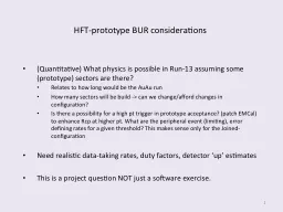
/
Pictorial view of 1973 simulation of core extrusion to test prototype hardware Pictorial view of 1973 simulation of core extrusion to test prototype hardware

Pictorial view of 1973 simulation of core extrusion to test prototype hardware - PowerPoint Presentation

emma
emma . @emma
Follow
65 views
Uploaded On 2023-10-04

Pictorial view of 1973 simulation of core extrusion to test prototype hardware - PPT Presentation

PURPOSE convey broad view of process sequence Actual 4cm drive tube extrusions were performed inside a nitrogen glovebox with more refined equipment Refer to SPP 70 for exact procedure J Allton ID: 1021942

1973 core extrusion simulation core 1973 simulation extrusion receptacle place top follower shown ram split removed clamp extruder tube

Share:

Link:

Embed:

Download Presentation from below link

Download Presentation The PPT/PDF document "Pictorial view of 1973 simulation of cor..." is the property of its rightful owner. Permission is granted to download and print the materials on this web site for personal, non-commercial use only, and to display it on your personal computer provided you do not modify the materials and that you retain all copyright notices contained in the materials. By downloading content from our website, you accept the terms of this agreement.


Presentation Transcript

1. Pictorial view of 1973 simulation of core extrusion to test prototype hardwarePURPOSE- convey broad view of process sequenceActual 4-cm drive tube extrusions were performed inside a nitrogen glovebox with more refined equipmentRefer to SPP 70 for exact procedureJ Allton5/11/2018

2. 1973 CORE EXTRUSION SIMULATION - Extruder, receptacle

3. 1973 CORE EXTRUSION SIMULATION - Extruder, receptacle

4. 1973 CORE EXTRUSION SIMULATION – With core upside down, remove excess regolith to level surface in preparation for installation of ramNOTE – these views of handheld actions pictured in slides 5-7 are done with supporting hardware as shown at right from actual dissection of 15009 in nitrogen glovebox.

5. 1973 CORE EXTRUSION SIMULATION – install ram on bottom of core, hold in place by installing two halves of split clamp

6. 1973 CORE EXTRUSION SIMULATION – Prepare to install follower on top of core: 1) remove plug, 2) remove keeper (NOT SHOWN), 3) place follower in top of core barrelRemove keeper –Not shown

7. 1973 CORE EXTRUSION SIMULATION – 1) place core tube with ram and follower installed into extruder, 2) remove split clamp (lead screw holding ram in place)

8. 1973 CORE EXTRUSION SIMULATION – 1) fine tune alignment and tension holding ram in place, 2) fasten clamps to hold tube firmly

9. 1973 CORE EXTRUSION SIMULATION –1) Align tube into receptacle, 2) mate receptacle to extruder – NOT SHOWN, 3) push regolith out of core tube into receptacle by turning the capstan wheel and advancing the lead screw.

10. 1973 CORE EXTRUSION SIMULATION – Regolith is completely pushed into receptacle, ram stem and lead screw threads visible between extruder and receptacle. Blue arrows show direction of push. Top of soil core is left, bottom is right on both images.

11. 1973 CORE EXTRUSION SIMULATION – Split clamp is re-installed to stabilize ram

12. 1973 CORE EXTRUSION SIMULATION – Install split clamp on follower to stabilize follower, install cover/handle over split clamp on follower end of core (top of soil column)NOTE – This process takes place before layered receptacle is removed from cart – not as shown here. Actual layered receptacle is made of Al 6061 except for top layer which is quartz (NOT IN PLASTIC AS SHOWN HERE)

13. 1973 CORE EXTRUSION SIMULATION – “Quartz” top layer is removed. This work is done when this assembly is mounted on a special stand, not directly on glovebox floor, as pictured here.

14. 1973 CORE EXTRUSION SIMULATION – The soil is removed is successive passes. As each pass (top to bottom of soil column) is removed another layer in the receptacle is removed to expose lunar material. This prototype layered receptacle is plastic, the flight sample receptacle is Al 6061; however, this plastic prototype allows visualization of the many screws holding each layer precisely in place.