/
Using EsterelC to Model and Verify the PIC16F84 Microcontroller  Mins Using EsterelC to Model and Verify the PIC16F84 Microcontroller  Mins

Using EsterelC to Model and Verify the PIC16F84 Microcontroller Mins - PDF document

faith
faith . @faith
Follow
344 views
Uploaded On 2021-09-10

Using EsterelC to Model and Verify the PIC16F84 Microcontroller Mins - PPT Presentation

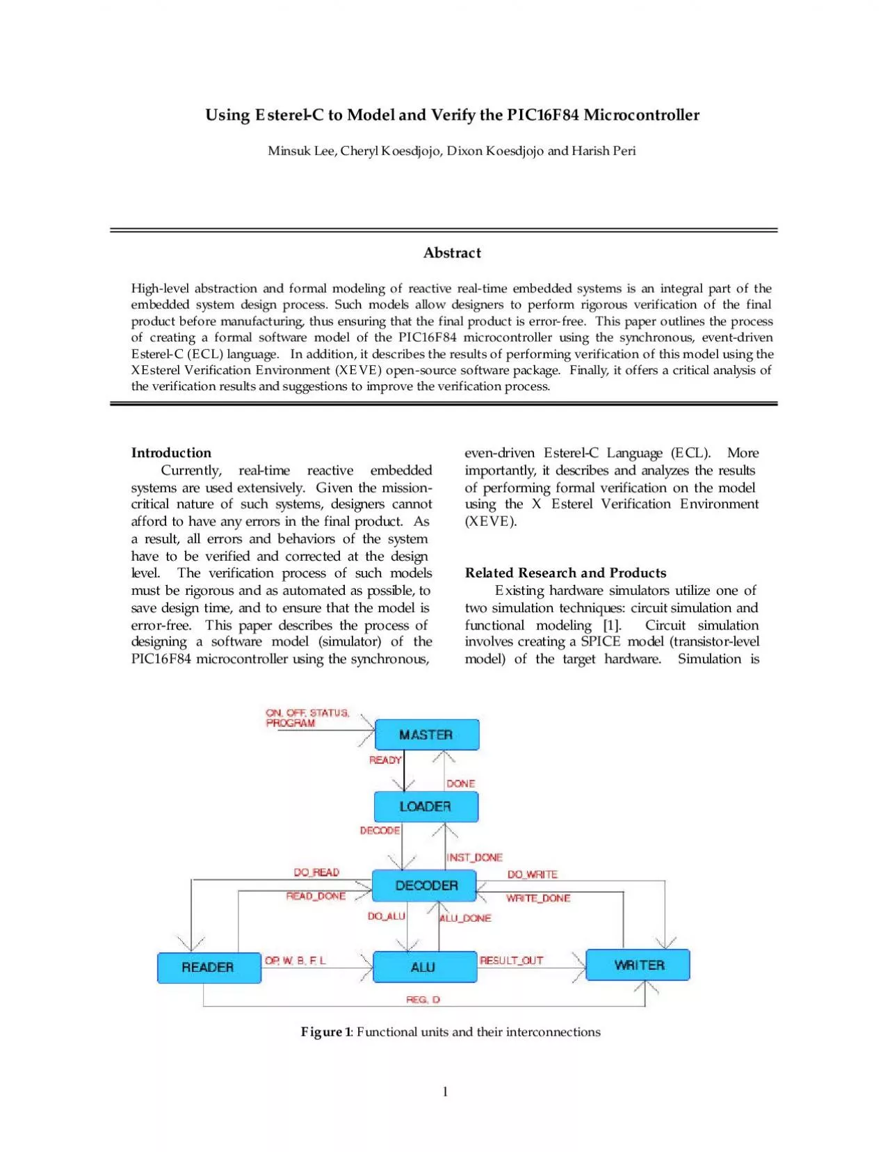
1Figure 1 Functional units and their interconnections 2performed by measuring the voltage and current outputs of the model in response to different input signals This is fundamentally different from ID: 878432

model alu output verification alu model verification output signals decode read signal opcode inst master doread x0000 doalu val

Share:

Link:

Embed:

Download Presentation from below link

Download Pdf The PPT/PDF document "Using EsterelC to Model and Verify the P..." is the property of its rightful owner. Permission is granted to download and print the materials on this web site for personal, non-commercial use only, and to display it on your personal computer provided you do not modify the materials and that you retain all copyright notices contained in the materials. By downloading content from our website, you accept the terms of this agreement.


Presentation Transcript

1 1 Using Esterel-C to Model and Verify
1 Using Esterel-C to Model and Verify the PIC16F84 Microcontroller Minsuk Lee, Cheryl Koesdjojo, Dixon Koesdjojo and Harish Peri Abstract Highlevel abstraction and formal modeling of reactive real-time embedded systems is an integral part of the embedded system design process. Such models allow designers to perform rigorous verification of the final product before manufacturing, thus ensuring that the final product is error-free. This paper outlines the process of creating a formal software model of the PIC16F84 microcontroller using the synchronous, event-driven EsterelC (ECL) language. In addition, it describes the results of performing verification of this model using the XEsterel Verification Environment (XEVE) open-source software package. Finally, it offers a critical analysis of the verification results and suggestions to improve the verification process. Introduction Currently, real-time reactive embedded systems are used extensively. Given the mission-critical nature of such systems, designers cannot afford to have any errors in the final product. As a result, all errors and behaviors of the system have to be verified and corrected at the design level. The verification process of such models must be rigorous and as automated as possible, to save design time, and to ensure that the model is errorfree. This paper describes the process of designing a software model (simulator) of the PIC16F84 microcontroller using the synchronous, evendriven Esterel-C Language (ECL). More importantly, it describes and analyzes the results of performing formal verification on the model using the X Esterel Verification Environment (XEVE). Related Research and Products Existing hardware simulators utilize one of two simulation techniques: circuit simulation and functional modeling [1]. Circuit simulation involves creating a SPICE model (transistor-level model) of the target hardware. Simulation is Figure 1: Functional units and their interconnections 2 performed by measuring the voltage and current outputs of the model in response to different input signals. This is fundamentally different from functional modeling, which involves decomposing the hardware into high-level functional units. In this kind of simulation, the target hardware is treated as collection of interconnected “black-boxe

2 s” that all have different function
s” that all have different functionalities. Despite the fundamental difference in simulation techniques, hardware simulators tend to have similar underlying architectures. The most widely used architecture for microprocessor simulators is the discrete-event architecture (DEA). Every decision in DEA simulators is in response to an event, which could be a new instruction or an external stimulus [2]. Events are triggered in response to an internal clock or some form of discrete time system and the result of processing the event are to change the overall state of the system. Currently, there are three main software simulators for the PIC16F8X family of chips. All of these three simulators allow only functional modeling type of simulation to be performed based DEA. These are: ? MPSIM: Discreteevent simulator [3] designed for debugging software applications made for the PIC16FXX family of chips. It offers the user the ability to place breakpoints in the code and perform stepstep execution of programs. In addition, it offers a register-browser, code-browser and I/O pin monitor. Program execution can be frozen midway and instructions can be changed on the fly. Contents of the execution stack can be observed at all times. ? GPSIM: Full-featured simulator [4] for the PIC microcontrollers distributed under the GNU General Public License. It includes simulation of all the core I/O pins and can be subject to external stimuli. It also includes a register state browser, code browser, debugger and I/O pin monitor. It is implemented entirely in C and can be used only on a Linux system. ? Universal Microprocessor Program Simulator: This simulator has the ability to model a variety of existing microcontrollers in addition to the PIC series [5]. It possesses all the functionality of GPSIM, but also includes a variety of hardware external devices (such as a 7-segment LED and D/A converter) that are not specific to the PIC chips. Design – Decisions and Rationale Unlike the simulators described above, this implementation (hereto referred to as ESIM) does not encompass the complete functionality of the PIC16F84 microcontroller. Since the ultimate goal of this project is to perform formal verification, complete emulation is be beyond the scope of this research. Functionality that has been sacrificed includes

3 the ability to define and use subroutine
the ability to define and use subroutines and the ability to perform external I/O. The other simulators are meant to be complete debugging environments for PIC16F84 assembly programs. They have been created after rigorous verification of their target hardware. In contrast, ESIM is meant to be an example of a foolproof model against which the final hardware, or its circuit simulation can be crosschecked. This also explains why ESIM is implemented in ECL, as opposed to an inherently nondeterministic language like C, or C++. Determinism allows the verification of the model to be automated, reliable and thorough. ESIM consists of six Esterel modules (Figure 1): master, loader (Program Memory), decoder (Instruction Decode and Control), reader, ALU (Arithmetic Logic Unit) and writer (EEPROM Data Memory). The names of the actual functional units on the chip are in parentheses [6]. Modules communicate exclusively through Esterel signals. When multiple modules are signaled successively, the “calling” module waits for a return response from the first “callee” module before emitting its par loader(READY, INST_DONE, DECODE, DONE); par decoder(DECODE, READ_DONE, ALU_DONE, WRITE_DONE, DOREAD, DOALU, DOWRITE, INST_DONE); par reader(DOREAD, OP, W, D, F_VAL, B, L, READ_DONE, REG); par ALU(DOALU, W, OP, B, F_VAL, L, RESULT_OUT, ALU_DONE); par writer(DOWRITE, D, REG, RESULT_OUT, WRITE_DONE); Figure 2: Instantiation of the modules in parallel 3 next signal. In all cases, the wait for the return signal has been implemented as an “await immediate”. This makes sure that a callee module does not indefinitely await a signal that was present in the previous cycle and that there is no possibility for race conditions on global variables. More importantly, this correctly emulates the serial behavior of the processor. Esterel’s synchronous model does not allow state preservation, since a signal only exists in the context of one instant. Hence, elements of memory such as the code memory, program counter and register file are modeled as different kinds of C variables. They are all declared in global scope so that all appropriate modules can access them when needed. Since no two modules will ever be executing at the same time, there is no fear of the variable being overwritten with the wro

4 ng value. The master module instantiate
ng value. The master module instantiates all the modules in parallel (Figure 2). It sets up the intermodule communication pathways. The loader is then activated (via the READY signal), reads in the assembly program (using C file access routines) and stores it in an array of instructions. It iterates through this array emitting the DECODE signal for each instruction (Figure 3). The current instruction is stored in a global variable. The decoder module, upon receiving the DECODE signal, sets up to signal the reader, ALU, and the writer modules (Figure 4). The current instruction determines which modules are signaled. For instance, in the bitoriented operations (BTFSC BTFSS, BCF and BSF) the writer module is not signaled since no registers need to be updated. Control is then passed to the reader module (Figure 5), by the decoder’s emission of the DOREAD signal. The reader gets the appropriate values (from registers or instruction memory) and emits them as valued signals for use by the ALU. In addition, depending on the instruction, a signal indicating the write destination of the ALU computation may also be emitted. In the ALU module, the result of computation on the input valued signals is emitted (Figure 6). At the same time, a signal indicating ALU completion is also emitted so that the decoder can then signal the writer module (if necessary). Finally, the decoder signals the writer module with the DOWRITE signal. Using the while (PC ) { instruction_buffer = prog[PC]; emit(DEC await(); if (PC_MODIFIED == 0) PC++; else PC_MODIFIED = 0; } Figure 3: Emission of DECODE signal for each instruction opcode = instruction_buffer - �instruction.byte_instruction.opcode; if (opcode == 0x7 || opcode == 0x5 || opcode == 0x3 || opcode == 0x2 || opcode == 0x9 || opcode == 0x6 || opcode == 0xB || opcode == 0xA || opcode == 0xF || opcode == 0x4 || opcode == 0x8 || opcode == 0x1 || opcode == 0xD || opcode == 0xC || opcode == 0xE || opcode == 0x6 || opcode == 0x0) { emit(DOREAD); await(immediate(READ_DONE)); emit(DOALU); await (immediate(ALU_DONE)); emit(DOWRITE); await(immediate(WRITE_DONE)); emit(INST_DONE); } Figure 4: Signaling the reader, ALU, and writer modules w = REGS[W_REG]; f = REGS[instruction_buffer emit(OP, instruction_buffer- emit(D, instruction_buffer- emit(W, w

5 ); emit(F, f); emit(REG, instruction_buf
); emit(F, f); emit(REG, instruction_buffer- emit(READ_DONE); Figure 5: Emission of valued signals in reader module if ( B != 0) B = B - 1; F_VAL = F_VAL | (0x1 ) emit(RESULT_OUT, F_VAL); Figure 6: Emission of computation result in ALU 4 destination indicator signal (emitted in the reader module), the result of the ALU calculation is written to the appropriate register (Figure 7). Control is returned to the loader module via the INST_DONE signal, where the next instruction is fetched from the program memory (array). The PC variable is also incremented at this stage. Simulation and Verification Verifying that the model meets its specification is the most important part of the design process. If the model is completely accurate, then the output of the model can be used as a reference point to compare the output of a circuit simulation of the hardware. Any possible inconsistencies in the outputs can be used to correct the errors in the circuit simulation, thus ensuring that the final hardware will be reliable. In order for model verification to be performed rigorously, the model should be defined in a language that ensures determinism. This eliminates the possibility of unpredictable behaviors and allows the designers to systematically test the model against all possible inputs. ECL, the language used to design our model, is completely deterministic. This is a result of the inherent determinism of Esterel. Signals, which are the only means of communication in Esterel, can either be present or absent in any given cycle. In addition, signals do not persist across cycles and there are no shared variables. These properties of the language ensure that our model is completely deterministic. Verification of our model was a two-step process. First, we verified that the model accurately met its specifications in terms of processing all necessary assembly instructions correctly. Second, we verified the consistency and accuracy of signal emission in each component module of the model. In hardware terms, we verified that the “wires” in our circuit were carrying the correct values at all times. For the first part of the verification, we used the executable program created by the ECL compiler. We ran simple test assembly programs in our simulator. As far as possible, we tried to include (in va

6 rying combinations) all 35 instructions
rying combinations) all 35 instructions in the processor’s instruction set. In all test cases, the computed output was accurate, and the correct registers were read and written. Appendix 2 shows a sample run of the simulator. The assembly code used in this sample run, implements a 2bit binary down counter that counts d from 7 to 0. The second part of the verification involved testing the accuracy of signal emissions in the model. To automate this process, a GUI-based tool called XEsterel Verification Environment (XEVE) was used. This tool reads in the finite-state machine (FSM) representation of an Esterel program and gives the user the ability to check the emission of output signals for different combinations of input signals. A graphical representation of the finite state machine, created using a program called ATG, is shown in Appendix 1. In the case of our model, since the functionality is divided into six independent units, verification of the model as a whole is inadequate, as we would lose all internal signal information. Hence, six independent modules were written, by separating out the appropriate code sections from the simulator code. Verification was then performed on each one of these modules and output signals were observed. All six modules behaved as expected. In the case of the master, loader, decoder and writer modules, we successfully verified that the output signals (READY, DECODE, DO_READ, DO_WRITE, DO_ALU, WRITE_DONE) were present. For the reader, writer and ALU, we verified that the various signals that carried the computation results were emitted. Figures 8 and 9 show screenshots of the verification process of the ALU and reader respectively. await(DOWRITE); if (D == 0) { REGS[W_REG] = WRITE_VAL; emit(WRITE_DONE); } else if (D == 1) { REGS[REG] = WRITE_VAL; emit(WRITE_DONE); } Figure 7: Signaling the reader, ALU, and writer modules 5 Due to the design of our model, all signals emitted by the reader and ALU modules (with the exception of READ_DONE and ALU_DONE) had integer values. Verification for these modules would be through only when the values of each one of these signals were tested for different input values. Here, we ran into a serious limitation of XEVE, namely that we could only check for the “possible emission” of output signals and not

7 the values (if any) of those signals.
the values (if any) of those signals. This limitation is largely due to the fact that finite state machine (FSM) model that is used by XEVE is incapable of representing value-sed states. As seen in the FSM in Appendix 1, each state is a Boolean function of the possibly emitted signals. Verification Issues The verification process of our model exposed two major inadequacies of XEVE as a verification environment for complex functional models. First, there is no means by which we can check the values of the signals. This poses a serious problem in the case when the signal values are critically important to the functioning of the system. Inability to verify them might lead to the overlooking of major errors. XEVE has no means to allow complete automation of the verification process. In order to perform verification, the set of input and output signals that are present/absent have to be manually selected. Our model was designed in ECL to enable us to model memory and the PC. Hence, we did not have a very large number of signals in the entire system. However, in any eventdriven system that is designed solely using signals, i.e. solely in Esterel, there is the likelihood of using a very large number of signals. For instance, in a processor simulator, every bit of all the registers, the main memory and the program counter would have to be represented as separate signals. In such a system, making sure that all combinations of inputs yield the correct outputs can be a very difficult task. Not only will valuable design time be wasted, but there is also a very high probability of undetected errors in the highlevel model. The Ideal Verification Environment XES is a graphical simulator for Esterel programs. Unlike XEVE, there is no form of automation in XES. However, the designer has the ability to specify the values of the input signals and monitor the values of the output signals. Thus, XES is ideal for verifying those models that do not utilize too many signals for internal communication thus do not require automated verification. Ideally, a verification environment would have similar functionality to XES. To give the designer full flexibility over monitoring the values Figure 8: Verification of ALU module. The inadequacy of XEVE is evident since we cannot check the signal values Fig

8 ure 9: Verification of reader module.
ure 9: Verification of reader module. 6 of signals, the verifier should be a fully functional simulator of the model. More importantly, the verifier must have the ability to automate the entire verification process. To this end, the verifier should be able to create an FSM representation of the model that takes into account the values of the signals when creating the various states as opposed to just the absence/presence of the signals. This kind of FSM will be more succinct (Figure 10) than the FSM for a purely signal based model and will have equal computational capability. Moreover, rigorous verification will be made easier since all possible states and paths in the model can be examined. Conclusion A functional model of the PIC16F84 microcontroller was created using the ECL language. The model was created to represent the various functional units of the microcontroller. The model was verified in two stages. First, the overall functionality of the model was verified by running a test program. Then, the signal emission of each of the component modules was verified using the XEVE tool. The verification environment provided by XEVE is not adequate enough for rigorous verification, as the values of signals cannot be monitored or assigned. Moreover, since the finite state machine that XEVE uses is too large, fully automated verification is not supported. An ideal verification environment is one that allows signal assignment and monitoring and that provides for complete verification of the model. Current verification technologies for models created in eventbased languages such as ECL are lacking in functionality. Since languages such as ECL are very useful for creating high-level models of hardware, it is in the best interest of designers to make existing verification technologies more efficient and rigorous. Ultimately, this will accelerate the entire hardware creation process by leaps and bounds. A C = {0, 1, 2, 3} B Figure 10: In the signal-based FSM, the four target states (B1-B4) represent the four possible Boolean combinations of the output signals X and Y. Using value-based signals, these states can be reduced to one state (B) that represents the value of the emitted signal. If the signals X and Y were the individual bits of some 2-bit register, then we can see the consid

9 erable reduction that can be achieved on
erable reduction that can be achieved on the large scale Value - based FSM A XY = 11 B1 Purely signal - based FSM B2 XY = 10 XY =01 B3 B4 XY =00 7 Works Cited [1] “Proteus Virtual Modeling System.” Blitzlogic Inc. Nov. 2001 [2] Hossein, Arsham. “System Simulation: The Shortest Path from Learning to Application.” Nov 2001 http://ubmail.ubalt.edu/~harsham/simulation/sim.htm [3] “MPSIM™ Simulator for DOS Users Guide.” Microchip Corporation. Oct. 2001 http://www.microchip.com/download/tools/archive/mpsim/30021i.pdf� [4] Dattalo, Scott T. “gpsim.” 24 Dec. 1999. GNU General Public License. Oct. 2001 http://www.dattalo.com/gnupic/gpsim.ps [5] “Universal Microprocessor Program Simulator.” Virtual Micro Design. Oct. 2001 http://www.vmdesign.com/htm [6] “PIC16F84 Datasheet.” Microchip Corporation. &#xhttp;&#x://w;&#xww.m;&#xicro; hip;&#x.com;&#x/dow;&#xnloa; /li;&#xt/pl;&#xine/;&#xpicm;&#xicro;&#x/fam;&#xilie;&#xs/16;øx/;ぃ .p;� Oct 2001 Online sources are cited using the MLA format: Author name. Article name. Date created. Organization name. &#xURL0; Date accessed 8 $./processorM.exe �master ; --- Output: �master ON; POWER IS ON Please load a program. --- Output: �master program="t.p"; Running t.p WRITER: Destination W: Value=7 --- Output: DECODE READY INST_DONE DOREAD DOALU DOWRITE READ_DONE ALU_DONE WRITE_DONE OP(48) W(0) D(0) L(7) RESULT_OUT(7) �master ; Opcode: 0 F: 0 D: 1 WRITER: Destination Register 0: Value=7 --- Output: DECODE INST_DONE DOREAD DOALU DOWRITE READ_DONE ALU_DONE WRITE_DONE OP(0) W(7) D(1) RESULT_OUT(7) F_VAL(0) REG(0) �master ; Opcode: 3 F: 0 D: 1 WRITER: Destination Register 0: Value=6 --- Output: DECODE INST_DONE DOREAD DOALU DOWRITE READ_DONE ALU_DONE WRITE_DONE OP(3) W(7) D(1) RESULT_OUT(6) F_VAL(7) REG(0) �master ; --- Output: DECODE INST_DONE DOREAD DOALU READ_DONE ALU_DONE OP(7) B(2) F_VAL(0) REG(2) �master ; --- Output: DECODE INST_DONE DOREAD DOALU READ_DONE ALU_DONE OP(5) L(2) �master ; Opcode: 3 F: 0 D: 1 WRITER: Destination Register 0: Value=5 --- Output: DECODE INST_DONE DOREAD DOALU DOWRITE READ_DONE ALU_DONE

10 WRITE_DONE OP(3) W(7) D(1) RESULT_OUT(5
WRITE_DONE OP(3) W(7) D(1) RESULT_OUT(5) F_VAL(6) REG(0) �master ; --- Output: DECODE INST_DONE DOREAD DOALU READ_DONE ALU_DONE OP(7) B(2) F_VAL(0) REG(2) �master ; --- Output: DECODE INST_DONE DOREAD DOALU READ_DONE ALU_DONE OP(5) L(2) �master ; Opcode: 3 F: 0 D: 1 WRITER: Destination Register 0: Value=4 --- Output: DECODE INST_DONE DOREAD DOALU DOWRITE READ_DONE ALU_DONE WRITE_DONE OP(3) W(7) D(1) RESULT_OUT(4) F_VAL(5) REG(0) �master ; --- Output: DECODE INST_DONE DOREAD DOALU READ_DONE ALU_DONE OP(7) B(2) F_VAL(0) REG(2) �master ; --- Output: DECODE INST_DONE DOREAD DOALU READ_DONE ALU_DONE OP(5) L(2) �master ; Opcode: 3 F: 0 D: 1 WRITER: Destination Register 0: Value=3 --- Output: DECODE INST_DONE DOREAD DOALU DOWRITE READ_DONE ALU_DONE WRITE_DONE OP(3) W(7) D(1) RESULT_OUT(3) F_VAL(4) REG(0) �master ; --- Output: DECODE INST_DONE DOREAD DOALU READ_DONE ALU_DONE OP(7) B(2) F_VAL(0) REG(2) �master ; --- Output: DECODE INST_DONE DOREAD DOALU READ_DONE ALU_DONE OP(5) L(2) Opcode: 3 F: 0 D: 1 WRITER: Destination Register 0: Value=2 --- Output: DECODE INST_DONE DOREAD DOALU DOWRITE READ_DONE ALU_DONE WRITE_DONE OP(3) W(7) D(1) RESULT_OUT(2) F_VAL(3) REG(0) Appendix 1 Sample run of simulator counting numbers down from 7 to 0 9 --- Output: DECODE INST_DONE DOREAD DOALU READ_DONE ALU_DONE OP(7) B(2) F_VAL(0) REG(2) �master ; --- Output: DECODE INST_DONE DOREAD DOALU READ_DONE ALU_DONE OP(5) L(2) �master ; Opcode: 3 F: 0 D: 1 WRITER: Destination Register 0: Value=1 --- Output: DECODE INST_DONE DOREAD DOALU DOWRITE READ_DONE ALU_DONE WRITE_DONE OP(3) W(7) D(1) RESULT_OUT(1) F_VAL(2) REG(0) �master ; --- Output: DECODE INST_DONE DOREAD DOALU READ_DONE ALU_DONE OP(7) B(2) F_VAL(0) REG(2) �master ; --- Output: DECODE INST_DONE DOREAD DOALU READ_DONE ALU_DONE OP(5) L(2) �master ; Opcode: 3 F: 0 D: 1 WRITER: Destination Register 0: Value=0 --- Output: DECODE INST_DONE DOREAD DOALU DOWRITE READ_DONE ALU_DONE WRITE_DONE OP(3) W(7) D(1) RESULT_OUT(0) F_VAL(1) REG(0) �master ; --- Output: DECODE INST_DONE DOREAD DOALU READ_DONE ALU_DONE OP(7) B(2) F_VAL(4) REG(2) �master ; Program finished successfully! --- Output: DONE 10 Appendix 2 Finite state machine representation of the simulator generated