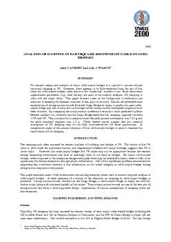
/
Associated Engineering, Burnaby, BC, Canada.Dept of Civil Engineering Associated Engineering, Burnaby, BC, Canada.Dept of Civil Engineering

Associated Engineering, Burnaby, BC, Canada.Dept of Civil Engineering - PDF document

faustina-dinatale
faustina-dinatale . @faustina-dinatale
Follow
485 views
Uploaded On 2015-11-01

Associated Engineering, Burnaby, BC, Canada.Dept of Civil Engineering - PPT Presentation

1468seismic design was based upon a 2 spectrum with additional checks being done for 1 Narita andYokoyama 1991 These values were selected because the bridge has welded steel towers and the gir ID: 179479

1468seismic design was based upon

Share:

Link:

Embed:

Download Presentation from below link

Download Pdf The PPT/PDF document "Associated Engineering, Burnaby, BC, Can..." is the property of its rightful owner. Permission is granted to download and print the materials on this web site for personal, non-commercial use only, and to display it on your personal computer provided you do not modify the materials and that you retain all copyright notices contained in the materials. By downloading content from our website, you accept the terms of this agreement.


Presentation Transcript

Associated Engineering, Burnaby, BC, Canada.Dept of Civil Engineering McMaster University, Hamiliton, Ontario, Canada.ANALYSIS OF DAMPING IN EARTHQUAKE RESPONSE OF CABLE-STAYEDBRIDGESJodie C ATKINS And John C WILSONSUMMARY 1468seismic design was based upon a 2% spectrum, with additional checks being done for 1% (Narita andYokoyama, 1991). These values were selected because the bridge has welded steel towers and the girder iscarried entirely by the cables, with no bearings at the towers (Kitazawa, 1999).The damping values used for wind design of cable-stayed bridges are distinctly different from the commonlyassumed 5% for seismic design. In Japan, the Wind Resistant Design Manual for Highway Bridges, assummarized by Narita and Yokoyama (1991), suggests damping should be considered in the range of 0.25 -0.5%. Scanlan and Jones (1990) have generally assumed 1% structural damping in all modes for aeroelasticanalysis of cable-stayed bridges.ComparisonThe difference in choice of damping for seismic and wind analysis is usually attributed to several factors. First,the dominant frequency range of earthquakes is higher than that of wind. This observation is associated with abelief that increased damping is associated with higher modes of vibration (such as those excited byearthquakes). Second, the primary aeroelastic modes of response to wind vibration are bending and torsion,whereas in earthquake response longitudinal and transverse modes often play a significant role. In this situation,horizontal modes of vibration can lead to dissipation of structural energy into the ground, subsequentlyincreasing the effective damping of the structure. Third, in seismic design some parts of the structure may beallowed to undergo limited plastic deformations that provide additional energy dissipation. Wind design, on theother hand, is based upon elastic response with no consideration of yielding of structural elements.DAMPING EVALUATED FROM MEASURED RESPONSES FO CABLE-STAYED BRIDGESAmbient vibration surveysAmbient vibration surveys (avs), designed to measure small amplitude responses to ambient (typically traffic andwind) excitations, have been performed on a number of bridges. Although ambient vibration measurements havewell-known limitations that can seriously affect an accurate determination of damping, they are nonetheless oneof the few sources of actual damping data. Measurements on the Tampico Bridge in Mexico, and on the I-295James River Bridge, concluded that nearly all modes exhibited damping less than 1%. Testing on the QuincyBayview Bridge indicated damping values to be generally less than 2% (Atkins, 1998). Aside from well-knownproblems of measurement error, one unresolved limitation of avs results are the extent to which they areapplicable for higher amplitudes of motion during a moderate to large earthquake.Forced vibration testingForced vibration tests have been conducted on a number of cable-stayed bridges, including Alex Fraser,Shipshaw, Alamillo and Tjorn Bridges. All of these tests indicated a generally low level of damping, with themajority of results giving values less than 1.5%, and with some results substantially below 1% (Atkins, 1998).Tests on Japanese cable-stayed bridges, reported by Narita and Yokoyama (1991), found damping valuesbetween 0.3% and 2%. This illustrates both the low levels and large spread in damping values.Strong-motion earthquake recordsFew cable-stayed bridges have been instrumented with strong-motion recording systems. The most completedata comes from two instrumented bridges in Japan - the Suigo Bridge in Chiba Prefecture (near Tokyo) and theHigashi-Kobe Bridge. This study has used the records from the Suigo Bridge to make estimates of dampingduring earthquake response. The Suigo records and complete structural details were readily available when thestudy was started.THE SUIGO BRIDGE AND STRONG MOTION RECORDSThe 290 m Suigo Bridge is illustrated in Figure 1. The bridge has a two span continuous cable-stayed part andapproach sections. The superstructure is a steel box girder connected both longitudinally and transversely to thesingle steel tower. Three cables connect to the centre of the girder in a single plane on each side of the tower. 1468Bearings at each end of the cable-stayed part allow free translation of the deck in the longitudinal direction butprovide restraint in the transverse direction. This study considers response of only the cable-stayed part.Locations of strong motion instrumentation in the longitudinal and transverse directions are marked by the sixcircled locations A1, etc., on Figure 1. The strong motion records used for this study were from the East Chiba-ken earthquake of December 17, 1987. The free-field (A6) peak ground acceleration (pga) was 1.14 m/s2(transverse) and 1m/s2 (longitudinal). At the top of the tower (A1) the pga was recorded as 10m/s2 (transverse)and 4.46 m/s2 (longitudinal), both rather large structural responses. These represent acceleration amplificationsof 8.8 (transverse) and 4.5 (longitudinal). At the centre of the longer span (A5) the pga was 3.63 m/s2(transverse) and 2.47 m/s2 (longitudinal).ANALYSIS OF SEISMIC RESPONSE OF SUIGO BRIDGEThe approach used to estimate the damping was to compare the actual strong motion records to structuralresponses computed using a calibrated finite element model of the bridge, with records from A6 (Figure 2) usedas inputs (Atkins, 1998). The finite element model was constructed using the SAP2000 program, based onstructural information provided by Kawashima et al., (1991). Damping was assumed to be viscous and constantin all modes. The finite element model was subjected to the longitudinal and transverse components of theground motions recorded at A6 (free-field). Responses were computed at the top of the tower and at the centreof the longer span (corresponding to instrument locations A1 and A5 on Figure 1, respectively) for dampingvalues of 0.5, 1, 2, and 5%. Foundation flexibility effects were included through the use of foundation springs,selected so that the frequency response characteristics of the model closely matched the Fourier spectralcharacteristics of the recorded earthquake responses. Summary details are provided in Table 1. No allowancewas made for foundation damping for reasons that will become apparent later. The dynamic characteristics ofthis model were in good agreement with forced vibration tests conducted by Japanese engineers (Kawashima etal., 1991). Although twenty modes were included in the seismic analyses conducted in this study, most of theresponses in each of the longitudinal and transverse directions resulted from participation of only a few modes.The modal participation factors associated with each of the main modes are indicated in Table 1. This is incontrast to the greater number of modes that must be used for many other larger and more complex cable-stayedbridges. The Suigo Bridge's relative simplicity in structural form, and the fact that responses in the longitudinaland transverse directions are largely uncoupled made it an ideal structure for this type of study.Table 1 Dynamic characteristics of the Suigo Bridge obtained by finite element analysis and bymeasurement MeasurementLocationFinite ElementModel Frequency () Modal Participation (%) Measured BridgeFrequency Lon itudinal: A11.50991.55 A51.501.55 Transverse: A10.75250.73 A51.03681.35 Locations: A1=top of tower; A5=centre of longer girder spanRESULTSFigure 3 shows, as an example, time history responses computed at the top of the tower (A1) for variousdamping ratios. The model responses for the various damping values were compared to the actual accelerationrecords in terms of their maximum response, duration of strong motion, and envelope of the acceleration record.The best matches of the model responses to the actual bridge responses (as determined by visually matching thetime histories) at locations A1 and A5 are shown in Figure 4. In each case separate matches were done for the 0-20 sec, and 20-40 sec segments of each record, and in some cases different 'best match' damping ratios wereidentified for these two time segments. These are summarized in Table 2. Although some refinement couldpossibly be made in the best match estimates by computing responses for more closely spaced damping values, itseemed that this was really not warranted. This is illustrated in the later section on comparisons of responsespectrum values. 1468Table 2 Best match estimates of the damping ratio for the Suigo BridgeMeasurement LocationFinite ElementModel*[0-20 sec]Finite Element Model*[20-40 sec]Japanese Analysis** A1 - lon g itudinal0.5 %2 %2 % A5 - lon g itudinal2 %5 %5 % A1 - transverse1 %1 %0 %-1 % A5 - transverse1 %2 %5 % * this study; ** Kawashima et al., (1991)DUSCUSSION OF RESULTSThe time histories in Figure 3 for the responses at the top of the tower for the various damping ratios clearlyshow the strong influence of damping on the amplitude of structural response. The stronger ground motionoccurred in the 0-20 sec segment, as shown in Figure 2. For computed responses within this interval the ratiobetween maximum response amplitude for 0.5% and 5% damping was approximately 2 for the longitudinaldirection and 1.5 for the transverse direction (responses are shown here only for A1 location).Figure 4 and Table 2 show that for the 0-20 sec segment, which contains the strongest input ground motion, bestmatch damping values were identified between 0.5% and 2%, values well-below those commonly assumed indesign. Because of the nature of this analysis, these damping estimates inherently include any damping thatmight be associated with the soil and foundations. One of the causes of such low damping may well be thecontinuous and integral nature of this all-steel bridge that offers very little in the form of energy dissipatingmechanisms.In three of four cases (Figures 4a, b, d) higher damping values were identified in the 20-40 second segment afterthe strongest ground motion was over. However, in two of these (Figures 4a,d) the best match damping wasfound to increase to only 2%, and in one case (Figure 4c) the best match damping was 1% over the entire record.In only one case (Figure 4b; location A5 longitudinal) was damping identified as high as 5%. These higherdamping values in the later part of the records are believed to be an artifact of the analysis resulting from thepresence of feedback of structural response in the recorded motion at A6, rather than an actual increase in systemdamping late in the response. This can be discerned in the A6 motions in Figure 2 after 20 seconds. Using thisas input to the finite element model would require a higher damping value be used to suppress response of thesystem to match the observed amplitudes of actual response.Of interest is an earlier study of the damping for the Suigo Bridge performed by Kawashima et al., (1991). Table2 includes the results from that study. Although that study had a similar approach to the present one, there aresome significant differences. The Japanese results indicate a best match damping of 5% for the girder in boththe longitudinal and transverse directions, and between 0% and 2% for motions measured at the top of thetowers. One of the principal reasons for the differences is believed to be the use of A3 motions as input. SinceA3 is on the base of the tower the recorded motions at this location already contain some of the structuralresponses in the form of feedback (as evident in Fourier spectra of A3, not shown here). Damping estimatesobtained using A3 motions as inputs are therefore expected to be higher than those found in this study using A6free field input. It would seem that using A6 is a more reasonable choice for the ground motion.The very limited results presented here seem to support the notion of low damping in cable-stayed bridges that isexpressed in many of the literature studies. Additional analyses of these records, and those of the Higashi-KobeBridge, could be used to obtain additional information on the damping characteristics of all-steel cable-stayedbridges. The implications of low damping values on seismic response of cable-stayed bridges is examined in thefollowing section.COMPARISIONS OF STRUCTURAL RESPONSES AT LOW DAMPINGComputed seismic responses of four cable-stayed bridges of various designs were examined for low dampingratios. One of these was the Suigo Bridge, and finite element models of the other three, referred to here asBridges 2-4, are shown in Figure 5. Each bridge was subjected to 3-D response spectrum analyses for 0.5%, 1%,2% and 5% damping, calculated from an ensemble average of 15 time history records containing significant 1468components in the longer period range. Moments and shears at the base of the towers for the two horizontaldirections (a total of four quantities) were computed for each spectral damping. The results of these comparisonsare summarized in Table 3 where responses at 0.5, 1 and 2% damping are expressed as ratios of the response at5%. The range of amplification ratios (shown in parentheses) for the four response quantities is generally small.Considering the ratios for all four bridges gives approximate average response amplifications of 1.3 for 2%damping, 1.5 for 1%, and 1.7 for 0.5%. These values provide a direct indication of the higher average responsesthat can occur at these lower damping values, and hence the potential consequences associated with a possiblyunconservative choice of 5%. More detailed discussions on these analyses are provided by Atkins (1998).Table 3 Mean ratios of responses (for moments and shears at the base of the towers) for low dampingvalues;referenced to responses at 5% damping Brid g eDam o1.721.531.32 Brid e 21.901.641.34 Brid e 31.641.451.24 Brid e 41.471.351.21 (Values in parentheses show range of ratios)CONCLUSIONSEvidence suggests that use of 5% damping for seismic response analysis of cable-stayed bridges may not be anappropriate, nor conservative assumption. Vibration tests on many cable-stayed bridges over the past decade orso have alluded to the possibility of this situation, and most arguments suggest that the low damping observed inthese tests is associated with the low amplitudes of motion. At higher response levels occurring duringearthquakes the damping would be expected to be larger. Although the data is very limited, the strong motionrecords from the Suigo Bridge show that low damping can exist during earthquake motions even when peakstructural response was 1.0 g. Damping values in the range of 1% - 2%, and as low as 0.5% have been inferredfrom this data. A response spectrum study of four cable-stayed bridges of representing various designs indicatesillustrates the implication of low damping. Average response amplification ratios (compared to responses for5% damping) for shear force and moment at the base of the towers of up to 1.7 were found when damping was aslow as 0.5%, with individual response quantity amplifications being as large as 2.1. For 2% damping theaverage response amplification was 1.3, and for 1% damping it was 1.5. These results also indicate that, for aparticular bridge, there is a need to conduct response sensitivity analyses to examine the impact of variousdamping assumptions on the computed seismic response.ACKNOWLEDGEMENTSThe financial support of the Natural Sciences and Engineering Research Council of Canada in the form of aPost-Graduate Scholarship to the first author and Research Grants to the second author and are gratefullyacknowledged. The structural information and strong motion records from the Suigo Bridge were kindlysupplied by K. Kawashima and S. Unjoh.REFERENCESAtkins, J.C., (1998) "Analysis of damping exhibited by cable-stayed bridges during seismic events", MEngThesis, Department of Civil Engineering, McMaster University, Hamilton, Ontario.Kawashima, K., Unjoh, S. and Tsunomoto, M., (1991), "Damping characteristics of cable-stayed bridges forseismic design", Journal of Research, Public Works Research Institute, Ministry of Construction, Tsukuba,Japan.Kitazawa, M., (1999), Hanshin Expressway Public Corporation, Osaka, Japan, personal communicationNarita, N., and Yokoyama, K., (1991), "A summarized account of damping capacity and measures against windaction in cable-stayed bridges in Japan", Cable-stayed bridges: recent developments and their future (M. Ito,editor), Elsevier Science Publishers.Scanlan, R.H., and Jones, N.P., (1990), "Aeroelastic analysis of cable-stayed bridges", ASCE, Journal ofStructural Engineering, Vol.116, No.2. 1468Figure 1 The Suigo Bridge showing strong motion instrument locations A1 to A6 (Kawashima et al; 1991) Longitudinal Acceleration Record, A6-1.5-0.50.51.5010203040Time (seconds) Tranverse Acceleration Record, A6-1.5-0.50.51.5010203040Time (seconds) Figure 2 Ground accelerations recorded by down-hole accelerometer at location A 1/2% Damping051015202530354045 1/2% Damping-20-10051015202530354045 1% Damping051015202530354045 1% Damping-20-10051015202530354045 2% Damping051015202530354045 2% Damping-20-10051015202530354045 5% Damping051015202530354045Time (seconds) 5% Damping-20-10051015202530354045Time (seconds)(a) Longitudinal at A(b) Transverse at AFigure 3 Response accelerations computed at the top of the tower (A) for 0.5, 1, 2 and 5% dampingwhen subjected to A motions as input 1468 -14-100510152025303540Time (seconds) Model 2 (1% Damping) Actual Record 0510152025303540Time (seconds) Model 2 (0.5% Damping for 0-20 seconds, 2% Damping for 20-40 seconds) Actual Record (a) Longitudinal direction at top of tower (A)(c) Transverse direction at top of tower (A 0510152025303540Time (seconds) Model 2 (1% Damping 0-20 seconds, 2% Damping 20-40 seconds) Actual Record 0510152025303540Time (seconds) Model 2 (2% Damping for 0-20 seconds, 5% Damping for 20-40 seconds) Actual Record (b) Longitudinal direction at centre of longer span (A) (d) Transverse direction at centre of longer span (AFigure 4 Comparisons of accelerations from recorded (actual) responses and best matched dampedresponses from finite element model for Suigo Bridge Figure 5 Three additional cable-stayed bridges used in response spectrum study(centre span length and fundamental period are shown for each) Associated Engineering, Burnaby, BC, Canada.Dept of Civil Engineering McMaster University, Hamiliton, Ontario, Canada.STRUCTURAL MATERIALS, ELEMENTS AND SYSTEMS, Acceleration records, Dynamic response, Seismic analysis, Strong motionrecords, Structural damping, Structural response, Viscous, Cable stayed bridge, Low damping,ANALYSIS OF DAMPING IN EARTHQUAKE RESPONSE OF CABLE-STAYED BRIDGESJodie C ATKINS And John C WILSONAbstractFor seismic design and analysis of major cable-stayed bridges it is typical to assume viscous structural dampingat 5%. However, there appears to be little empirical basis for use of this value for cable-stayed bridges, otherthan it is the "traditional" number to use. Even when more sophisticated procedures (e.g., time history) are usedin the seismic analyses, 5% damping is often still the target value. This paper reviews some of the backgroundto evaluation and selection of damping for dynamic response of this type of structure. Results are presentedfrom examination of strong motion records from the Suigo Bridge in Japan, a simple two-span cable-stayedbridge and one of only two such bridges where strong motion earthquake responses have been obtained. Bycomparing the actual seismic acceleration records to those predicted by finite element analysis it is observed thatthe Suigo Bridge exhibited low damping, typically between 0.5% and 2%. This occurred for a situation wherethe peak ground acceleration was 0.12 g and the peak structural response was 1.0 g. These limited resultssuggest that the common assumption of 5% damping may be too high (unconservative) for some applications. Acomparative study of the seismic response of four cable-stayed bridges is used to examine the implications oflow damping