/
NSRP  All Panel Meeting NSRP  All Panel Meeting

NSRP All Panel Meeting - PowerPoint Presentation

faustina-dinatale
faustina-dinatale . @faustina-dinatale
Follow
343 views
Uploaded On 2019-11-22

NSRP All Panel Meeting - PPT Presentation

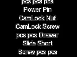
NSRP All Panel Meeting Selfsealing Cable Transi t Panel Project Update Terry Mannion Manager Marine Sector Development March 14 2019 Exhibit Table 2 Cable changes onboard naval vessels can be quite frequent due to mission changes and other technology upgrades The selfsealing cable tr ID: 766927

cable path view 150 path cable 150 view shock deck bulkhead marine testing aluminum steel assembly fire mil 2019

Share:

Link:

Embed:

Download Presentation from below link

Download Presentation The PPT/PDF document "NSRP All Panel Meeting" is the property of its rightful owner. Permission is granted to download and print the materials on this web site for personal, non-commercial use only, and to display it on your personal computer provided you do not modify the materials and that you retain all copyright notices contained in the materials. By downloading content from our website, you accept the terms of this agreement.


Presentation Transcript

NSRP All Panel Meeting Self-sealing Cable Transit Panel Project Update Terry MannionManager Marine Sector DevelopmentMarch 14, 2019 Exhibit Table 2

Cable changes onboard naval vessels can be quite frequent due to mission changes and other technology upgrades. The self‐sealing cable transit device provides increased safety by ensuring that the cable transits are always properly sealed for fire and smoke, while also allowing lifetime easy access to make cable changes, technology upgrades, and emergency cable pulls. The devices are intended for divisions not required to be watertight, such as the Bridge and other areas of ships above the v‐line. Once the device is installed, it is completely fire stopped and activation is simply insertion of the cable without and putty, sealant, nor compression blocks.

Topics Product DescriptionComponentsAttachment Installation Photos Assembly Details N-30 Deck N-30 Bulkhead Testing Overview Timeline Questions Exhibit Table 2

1 5 2 3 4 5 Key - MDM150C (Marine EZ-Path 150 for Aluminum Divisions) No.Part No.DescriptionQty.1MDM150EZ-Path 150 Pathway12MPASSY838MDM150C Intumescent Gasket13MP2504EZ-Path 150 Intumescent Wrap14ZLB1792MDM150C Nameplate15MP2506MDM150 Aluminum Attachment Plate2 Cat No.: MDM150CExploded View : Cat No.: MDM150C Product Description

1 6 2 4 3 5 Item: EZ-Path 150 Exploded View : Item: EZ-Path 150 4 5 6 7 7 77Key - MDM150 (Marine EZ-Path 150 Pathway)No.Part No.DescriptionHalf Qty.Total Qty.1-EZ-Path 150 Half Assembly-22MP1720EZ-Path 150 L-Channel 12 3 MP1366 150mm Marine Pathway Foam Pad 1 2 4 MP1772 EZ-Path 150 Marine "U" Pad Holder 2 4 5 MP1415 Marine Cable Transit Brush 150mm 2 4 6 MP1753 EZ-Path 150 Brush Seal Holder247ZRM0045#6 x 5/16" Torx Flat Thread Cutting Screw24 Product Description

Key - MDM150 (Marine EZ-Path 150 Pathway) No. Part No. Description T o t a l Qt y. 1 - Aluminum Deck or Bulkhead Plate 1 2 -1/4"-20 Stainless Steel Bolts 43MDM150CMarine EZ-Path 150 for Aluminum Divisions14-Flat Nylon Washer for 1/4" Screw Size45-1/4"-20 Stainless Steel Locknut4MDM150C Deck Installation Exploded View :5 1 4 3 5 5 5 2 2 2 4 4 4 2 2 Attachment

`2 Key - MDM150 (Marine EZ-Path 150 Pathway) No. Part No. Description T o t a l Qt y. 1 - Aluminum Deck or Bulkhead Plate12-1/4"-20 Stainless Steel Bolts 43MDM150CMarine EZ-Path 150 for Aluminum Divisions14-Flat Nylon Washer for 1/4" Screw Size45-1/4"-20 Stainless Steel Locknut4Nut and Bolt Attachment1 2 3 5 4 Attachment

Where will these devices be used ?Non Watertight Fire boundariesFoundations for Control Panels Deck and Bulkhead penetrations ExhibitTable 2

Assembly DetailN-30 DeckExhibitTable 2

N-30 Deck-Insulation & Pin Layout

N-30 Deck - Continued

Deck Shock Test Fixture91”L x 52”W x 46” H5” Square Steel Tube x 0.25” thick3” Square Steel Tube x 0.25” thick Angled Supports1” thick Steel Base Plate Weight – 2500 lbs Side View End View

N-30 Deck & Shock Fixture Aluminum Deck – Top View Over Shock Fixture

N-30 Deck Shock Test AssemblySide View End View Attachment Cable Support Cable Support Welds

Deck Shock Test Assembly Bottom View Cable T r ans i t s Cable Transits

Assembly Detail N-30 BulkheadExhibitTable 2

N-30 Bulkhead – Insulation and Pin Layout (Non-Fire Side)

N-30 Bulkhead – Insulation and Pin Layout (Fire Side)

N-30 Bulkhead - Continued

Bulkhead Shock Assembly FixtureFigure 15 Fixture in MIL-DTL-901EFront View Side View

N-30 Bulkhead & Shock Fixture Aluminum Bulkhead – Front View Over Shock Fixture

Bulkhead Shock Test Assembly Side View Front View Cable T r ans i t s Cable Transits Attachment

Testing OverviewVibration Testing per MIL-STD-167-1AFrequency Range of 4Hz through 33Hz in each of the 3 major axes Shock Testing to MIL-DTL-901EAssemblies subjected to a 7 blow Grade A, Class I, Type A, medium weight shock testFire resistance in accordance with MIL-STD-3020 30 minute fire resistance Max temp. rise of 181 ° C over initial temp. Hose stream testing in accordance with MIL-STD-3020 207kPa of water pressure through 28.5mm nozzle @ 0.11min/m ² of exposed area.

Testing OverviewToxicity testing per MIL-DTL-24705B Samples and SDS sent to Navy and Marine Corps Public Health Center ExhibitTable 2

Tentative Test ScheduleVibration Testing (Nu -Labs)Scheduled 14 March 2019 Shock Testing (Nu -Labs) Scheduled 14 March 2019 Fire & Hose Stream Testing ( SwRI) Complete by end of April 2019 Final Report Submit by End of May 2019 Exhibit Table 2

Questions?Support Contact:Marine Technical Services 800-992-1180Email: techserv@stimarine.com / www.stimarine.com Sr. Engineering Manager 908-526-8000 ext: 1034 Julio Lopes, CFPS, Email: jlopes@stimarine.com Manager of Marine Sector Development 410-963-1160 Terry Mannion, Email: tmannion@stimarine.com Exhibit Table 2