/
Find the best route through ice Find the best route through ice

Find the best route through ice - PDF document

freya
freya . @freya
Follow
344 views
Uploaded On 2021-08-05

Find the best route through ice - PPT Presentation

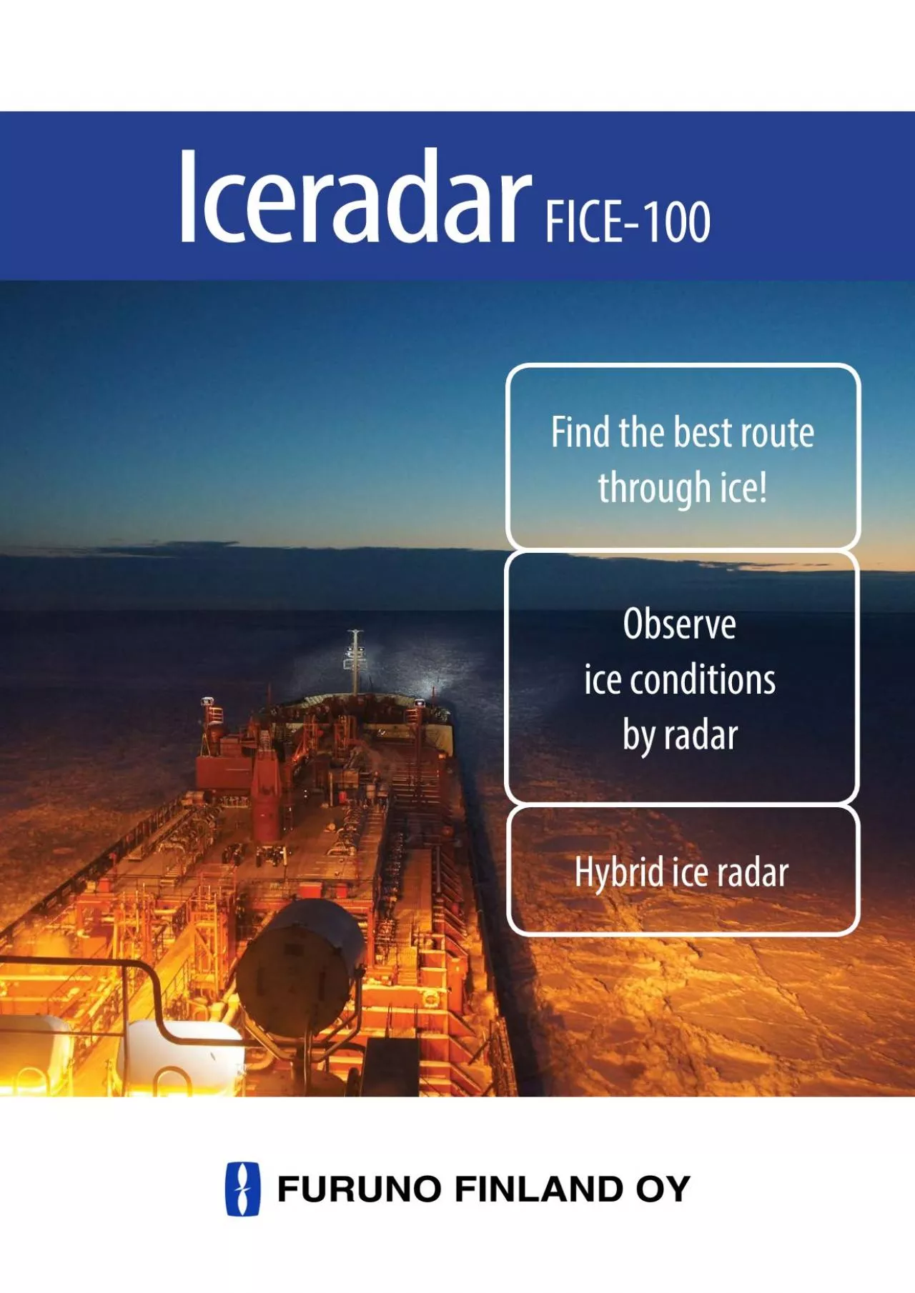
IceradarObserve ice conditions by radarHybrid ice radarVisualizes ice structures Discovers the optimum route to go through ice Shows the track in bad visibility Usable ice detection up to 4 NM Improv ID: 857519

ice radar cable oil radar ice oil cable spill standard video fice display navigation raw image 100 signal furuno

Share:

Link:

Embed:

Download Presentation from below link

Download Pdf The PPT/PDF document "Find the best route through ice" is the property of its rightful owner. Permission is granted to download and print the materials on this web site for personal, non-commercial use only, and to display it on your personal computer provided you do not modify the materials and that you retain all copyright notices contained in the materials. By downloading content from our website, you accept the terms of this agreement.


Presentation Transcript

1 Iceradar Find the best route through ice
Iceradar Find the best route through ice! Observe ice conditions by radarHybrid ice radar Visualizes ice structures. Discovers the optimum route to go through ice. Shows the track in bad visibility. Usable ice detection up to 4 NM. Improves stability of the ice picture compared to the radar. Increase safetyThe FICE-100 removes the image noise and the ne structures of the ice will become more visible. Hybrid ice radar captures the raw radar signal from the ARPA processor. The result is a stable image that includes the ne details found in the radar echos. It is

2 a supplementary system for the speci
a supplementary system for the specic task of observing ice conditions by radar. Ice radar displays the ice conditions Dicult ice conditions showing the three old broken ice-channels. Zoomed. Harbour view, showing the routes leave from the port and the port broken area. Vessels can nd the old rifts, clean ice and channels done by icebreakers and other vessels. The vessel uses much less power and saves fuel and time! Use less power Enhanced functionalities: FICE-100 is an alternative to IR camera. FICE-100 can also display ocial ENC chart material. Char

3 t can be overlaid with ice radar picture
t can be overlaid with ice radar picture. A clear broken ice-channel in the direction of 333.0 FOIL-200Oilradar Oil spill detection radar Observe and mark by radarHybrid oil radar Oil spill detection radar can be used in oshore and onshore installations together with standard navigation radar. The installation can be done onboard the vessels, oil rigs or any other platform where the radar is needed to detect oil spills. Oil radar for oshore and onshore installations The Oil Radar detects oil spills automatically and creates a polygon

4 to mark the spill. You can also mark the
to mark the spill. You can also mark the oil spills manually with polygons and update them whenever it is required.You can also take screenshots from the screen and record the raw radar video to the external hard disc or memory stick for future evaluation or training purpose. Navigation + oil radar picture. Green echoes from navigation radar, the rest is oil radar picture. Bright echoes are other ships with black shadow areas behind them. Dark area shown on the right side of the heading line is oil spill. FOIL-200 oil spill detection radar is connected to standard

5 Furuno FAR-2xx7 or FAR-3000 X-band na
Furuno FAR-2xx7 or FAR-3000 X-band navigation radar. It uses the raw radar video from the navigation radar. The special high performance algorithm is used to process and analyze the raw video to detect oil spills. To achieve the most ecient image to detect oil, you can change between dierent Fusion modes and see the result in real time on the screen. Oil spill image is created with an integration of up to 100 radar antenna scans. Generated image is based on motion compensated Fusion scans. Adjust the Fusion Scan number together with Fusion Mode. Process

6 and analyze the raw radar video Green p
and analyze the raw radar video Green polygon is marked by user. Oil spill is indicated as dark no-echo area on the screen www.furuno.Interconnection diagram SPECIFICATIONSIce radar processor - marine rack computerStandard1. FICE-110 Ice radar processorPower supply 100 - 230 VAC2. FICE-115 5 m Ice radar cableTrackball control unit3. FICE-130 2 m Control unit cableHigh resolution high bandwidth digitizer4. Standard spare parts and installation materialsIce radar display outputs DVI and VGARadar signalsOption1. Ice radar display w. cable (Specify when ordering)- rad

7 ar video and trigger - azimuth and headi
ar video and trigger - azimuth and heading line signals- standard cable length is 5 metersHeading, position and speed Your Furuno contact: www.furuno. Your Furuno contact: Interconnection diagram Standard Supply Option or Shipyard VGA/DVI OIL RADAR PROCESSOR FOIL-200 X-BAND RADAR 24 VDC or 115/230 VAC Position and SpeedCONTROL ROLLER Signal cable SPECIFICATIONSOil radar processor - marine rack computerStandard1. Oil radar processorPower supply 115/230 VAC, 50/60 Hz or 24 2. Signal cable for FAR-2xx7Trackball control unit3. Control unit with 2 m cableHig

8 h resolution high bandwidth digitizer14
h resolution high bandwidth digitizer14 bit, 60 MHz sample rate4. Standard spare parts and installation materialsOil radar display outputs DVI and VGARadar signals FAR-2xx7 or FAR-3000 X-band *)Option1. Oil radar display w. cable (Specify when ordering)- radar video and trigger2. Optional 10 and 30m signal cable for FAR-2xx7 - azimuth and heading line signals- standard cable length is 5 meters3. Optional 15, 30, 40 and 50 m signal cable for FAR-3000Heading, position and speed*) Minimum requirements for radar signals: Transceiver Antenna radiator 4 ft Gear box 24 rpm