/
BIOREMEDIATION IN BIOREMEDIATION IN

BIOREMEDIATION IN - PDF document

gagnon
gagnon . @gagnon
Follow
342 views
Uploaded On 2020-12-07

BIOREMEDIATION IN - PPT Presentation

FIELD PERSONNEL UNIT 
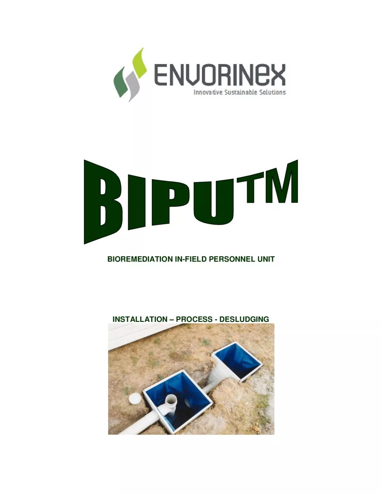
INSTALLATION PROCESS DESLUDGING BPU x0027eneral 4echnical nformation 2 BIPU GENERAL INFORMATION BIPU is a lightweight flat packed mini septic tank primary ID: 825804

bipu chamber treatment carcass chamber bipu carcass treatment liner pump site x0027 top sludge outlet water absorption nformation eneral

Share:

Link:

Embed:

Download Presentation from below link

Download Pdf The PPT/PDF document "BIOREMEDIATION IN" is the property of its rightful owner. Permission is granted to download and print the materials on this web site for personal, non-commercial use only, and to display it on your personal computer provided you do not modify the materials and that you retain all copyright notices contained in the materials. By downloading content from our website, you accept the terms of this agreement.


Presentation Transcript

BIOREMEDIATION IN-FIELD PERSONNEL UNIT
BIOREMEDIATION IN-FIELD PERSONNEL UNIT INSTALLATION – PROCESS - DESLUDGING B)PU™ 'eneral & 4echnical )nformation 2 BIPU GENERAL INFORMATION BIPU is a lightweight, flat-packed, mini septic tank primary treatment unit using a combination of variously configured Chambers certified in compliance with AS/NZS 1546.1:1999. BIPU Chambers Nominal carton pack size = 560 mm x 950 mm x 200 mm weighing 15 kgs BIPU uPVC 100mm DWV Pipes and Fittings are Quality Endorsed to AS3902/ISO9002 BIPU individual hollow carcass sections are designed to accept spoil once buried forming a ‘key’ effect with no buoyancy in variable ground water table sites and no problems in reactive soils. BIPU carcass in-ground hole size is 550mm x 550mm x 900mm with a pipe trench between the chambers connecting ‘A’ chamber to ‘B’ chamber to ‘C’ chamber or ‘A’ to ‘C’ etc as required. BIPU carcass Liner is a radio frequency seam and fitting welded polyester warp knit PVC material in a Semi-gloss coat finish with a fungal inhibitor displaying resistance to acids, alkalis and some solvents (as used for above ground swimming pools). The Liner is flame retardant with a Tensile Strength of 1300 x 1100 (AS2001.2.3); an Elongation at Break of 16 x 21 (AS2001.2.3) and a Wing Tear of 350 x 250 (AS2001.2.10). BIPU is designed so that the Liner can ‘float’ within the carc

ass where fluctuations in water table l
ass where fluctuations in water table levels occur to resist the ‘popping out of the ground’ syndrome (especially during times of infrequent use) with neutral buoyancy obtaining when the Chamber is charged with water. BIPU TOP shall be keyed to the BIPU carcass and extend beyond the carcass exterior by a minimum of 200mm so as to provide a raft to negate any potential effect of ground subsidence. Installation Issues – (a) Siting of BIPU Chambers Most BIPU Chambers will be sited in undeveloped remote areas, however when circumstances require installation in developed areas they should be installed clear of any buildings (so as not to affect any structural elements of the building) and away from vehicular driveways (b) Soils BIPU Chambers should be installed in stable soil conditions with areas of unconsolidated fill avoided. (c) Surface Water Surface waters should be diverted away from the BIPU Chambers by the installation of suitably constructed surface and/or sub-surface drains. (d) Location on Site The location of BIPU Chambers may be subject to approval by a regularity authority. (e) Drainage All drainage levels should be considered to ensure appropriate gradients to allow the gravity discharge of effluent into the top of the disposal area B)PU™ 'eneral & 4echnical )nformation 3 (f) Desludging The BIPU system should be sited with due consideration for fut

ure desludging operations and the posit
ure desludging operations and the positioning of the effluent treatment system. Where access for desludging by vehicle is not available the regularity authority will require a statement describing the intended method of desludging to be used so that it will not create a health nuisance (see BIPU Desludging Operators Manual). B)PU™ 'eneral & 4echnical )nformation 4 CHAMBER PACK CONTENTS A’ Chamber (Primary Treatment Zone) 205 litre capacity 1. Inlet 2. Pipe 3. Outlet to ‘B’ or ‘C’ Chamber 4. Carcass 5. Liner 6. Liner Clamp (4 pieces) ‘B’ Chamber (Primary Treatment Zone) 205 litre capacity 1. Inlet 2. Pipe 3. Inlet from ‘A’ and outlet to next Chamber 4. Carcass 5. Liner 6. Liner Clamp (4 pieces) ‘C’ Chamber (Liquid Retention Tank) 205 litre capacity 1. Inspection Opening/Tee / effluent outlet to secondary treatment or ‘D’ Chamber 2. Tail Pipe 3. Inlet from ‘A’ or ‘B’ Chamber 4. Carcass 5. Liner 6. Liner Clamp (4 pieces) ‘D’ Chamber (Liquid Holding Tank) 205 litre capacity 1. Inspection Opening/Cap 2. Inspection Opening Pipe 3. Inlet from ‘C’ Chamber / outlet to next Chamber 4. Carcass 5. Liner 6. Liner Clamp (4 pieces) 7. Top (Form Ply or Concrete Slab poured on site) B)PU™ 'eneral & 4echnical )nformation 5

‘E’ Chamber (Auxiliary Liquid H
‘E’ Chamber (Auxiliary Liquid Holding Tank) 205 litre capacity 1. Chamber has non handed connection capability to join with ‘D’ chamber and ‘F’ chamber or multiple ‘E’ chambers can be incorporated into the system to increase the liquid holding capacities. ‘F’ Chamber (Float Switch Activated Pump-out Tank) 205 litre capacity 1. Chamber has an inlet to join either ‘D’ or ‘E’ chamber; the inspection opening in ‘F’ chamber provides easy access for system pump out operations. E and F chambers are optional and are delivered flat packed in cartons ready for assembly on site requiring only your choice of cast concrete slab or form ply top, you will require the connecting 100mm DWV pipes as well as solvent primer and adhesive. B)PU™ 'eneral & 4echnical )nformation 6 BIPU INSTALLATION The BIPU must be installed by trade qualified persons in accordance with your regularity authority Installation Permit or a capable person using these instructions in conjunction with the nominated site specific absorption trench technology. If you have any problem, contact the BIPU Duty Officer. ‘A’ CHAMBER Step I - Lay one carcass side down with comer clips upward, mate the individual carcass sections onto the comer clips and then mate the other side; BIPU CARCASS UNIT is a recyclable hollow box section uPVC profile with injection moulded c

lick assembly corner fittings, factory f
lick assembly corner fittings, factory fitted into two sides. Simply click fit the non handed side sections onto the fitted corners to provide long life, extremely strong underground liner support and protection ensuring the clips are well home in the slots. Step 2 - Insert the carcass liner so that the outlet aligns with the hole in the carcass; Step 3 - Smooth the liner into the carcass comers, fold liner edges over the carcass, and slip on liner clamps; Step 4 - Ensure outlet is hard against the carcass interior, then glue fix the connecting pipe into the outlet spigot; Step 5 - Bed the carcass hole with suitable sand or soil, free from rock or other sharp objects, lower carcass into hole and connect the 100 mm outlet pipe to the next Chamber, Step 6 - Backfill around carcass and over connecting pipe with sand or soil, free from rock or other sharp objects. B)PU™ 'eneral & 4echnical )nformation 7 Step 7 – BIPU Top Permanent Installation - a concrete slab (thickness and carcass overhang to local specification) shall be poured and keyed to the BIPU carcass using galvanised screws through the Liner Clamp (run a bead of sealant over the top of the Liner Retention Clamps) and liner into the carcass; the slab shall allow for the 100 mm. Inspection Opening (I.O.) and waste entry and shall be supported by an earth bund around the carcass. BIPU Top Temporary Installation

- use a 19 mm Marine / Formply top
- use a 19 mm Marine / Formply top or similar (with a minimum of 200 min overhang beyond the carcass); run a bead of sealant all around the rim of the carcass over the top of each Liner Clamp (to provide a complete under top seal); locate and fix the top over the Chamber by screwing plated self tap screws through the top, the Liner Clamps and liner into the carcass with the top supported by an earth bund around the carcass. The top shall have provision for the 100 mm I.O. and another for the waste entry. Run a bead of sealant around the entry holes and insert each assembly, with the toilet bowl located inside a building the exterior BIPU may be installed up to a maximum of 2 metres from the toilet (for connection into the BIPU Chamber use a 100 mm elbow with an I.O. and a tail pipe length of 300 mm under the Chamber top. Step 8 - When all Chambers are installed charge the system with any convenient water - (BUT NOT SALT WATER) until the Tee invert level is reached in the ‘C’ Chamber. The effluent outflow from the ‘C’ Chamber will then connect with the sullage (grey water) line to either the on-site wastewater absorption system or to a holding Chamber with a submersible pump or to a bladder for cartage to a designated site effluent treatment site. B)PU™ 'eneral & 4echnical )nformation 8 Read the BIPU Operating Instructions and the system is then ready for use. Where a system ha

s not been operating for a period of tim
s not been operating for a period of time, inspect the in Chamber water levels and fill to the ‘C’ Chamber Tee invert level prior to use. ‘B’ CHAMBER PRIMARY TREATMENT ZONE Installation as for Chamber 'A' other than Step 4 where the ‘B’ Chamber inlet and outlet are treated the same as Chamber 'A' Step 4, ‘C’ CHAMBER LIQUID RETENTION Installation as for ‘A’ Chamber Steps 1, 2, 3, 6 and 8. Step 4 - Run a bead of sealant around the outlet hole orifice then locate the Tee Assembly (with long pipe section towards bottom of Chamber) into the outlet hole, prime then solvent cement the coupling (against the carcass) onto the outlet spigot. Where ‘C’ Chamber is to act as a receiving tank for pump-out purposes, the outlet spigot may be cut back to facilitate the cementing of a Push-On Cap onto the outlet spigot. Step 5 - Lower carcass into hole and connect inlet with the 100 mm connecting pipe from the ‘A’ 'or ‘B' Chamber as applicable, then connect the Outlet into the absorption trench unit. Step 7 - Run a bead of sealant around the carcass rim and around the head of the Tee, locate and install either a permanent or temporary top over the Chamber and fit the Push-On Cap onto the Tee. B)PU™ 'eneral & 4echnical )nformation 9 PRIMARY TREATMENT PROCESS The initial process of toilet wastewater purification occurs in

the BIPU Chambers which are designe
the BIPU Chambers which are designed and constructed to achieve Primary sewage treatment by facilitating the sedimentation and digestion sewage waste treatment process. Basic functions achieved in the BIPU are: - 1. Solids removal and commencement of sludge digestion; 2. Reduction of biochemical oxygen demand (BOD) of 10% (200mg/L to 180mg/L); 3. Complete denitrification to 75% inorganic and 25% organic nitrogen (N); 4. Conversion of most phosphates to orthophosphates; 5. Negligible removal of indicator organisms (reduction of E.Coli from about 12 million/100 ml to 11 million/100 ml). Sedimentation Sedimentation is a physical process of settling solids from the wastewater stream. The function of a BIPU system is to provide a relatively still zone of adequate size for the treatment of sewage wastewater at a predetermined flow rate. Based on an expected total water usage of 90 litres per person per day, the predicted flow rate of toilet wastewater will be between 15 litres and 20 litres per person per day. BIPU systems have the design capacity to allow a retention time of 24 hours to ensure solids are settled. Sedimentation has little effect on removal of pathogens or of their indicator organisms – the faecal coli forms. The BIPU design allows for the liquid above the settled solids (sludge) and below the scum layer to be discharged to where the final treatment and disposal processes occur. Digestion D

igestion is a biological process, which
igestion is a biological process, which occurs naturally as part of the carbon, oxygen, nitrogen and mineral cycles. Basically organisms, mainly micro-organisms, which feed on the dead organic matter present, carry out the treatment. The treatment process may be summarised as follows:- Carbon (C) Carbon Dioxide (CO2) Hydrogen (H) Water (H2O) Nitrogen (N) + Oxygen (O2) Micro organism Nitrates (NO3) Sulphur (S) Sulphates (SO4) Phosphorus (P) Phosphates (PO4) An oxygen supply is essential for decomposition and may be supplied either anaerobically or aerobically. B)PU™ 'eneral & 4echnical )nformation 10 Common decomposer organisms in sewage sludge include; Aerobic bacteria; Anaerobic bacteria; Protozoa; Metazoa; Algae; Fungi and Worms Decomposer Organism Living Conditions Aerobic bacteria Protozoa Metazoa Algae Fungi Worms Free Oxygen pH 4.5.to 8.5 (Optimum pH 7.0) Temperature 10 – 20 Celsius 20 – 40 Celsius 45 – 60 Celsius Anaerobic bacteria Protozoa Fungi Fixed Oxygen pH 4.5 to 8.5 Temperature 10 – 20 Celsius 20 – 40 Celsius (Optimum) 45 – 60 Celsiu

s Table 1 - Shows th
s Table 1 - Shows the optimum living conditions for these Common Decomposer Organisms found in sewage. BIPU systems have been designed to function as an anaerobic digester. The operation of digestion as the time required to decompose the solid organic material is temperature dependent. The organisms act fastest at around 30C ~ 35C (1). Mesophilic Digestion rates between 30C ~ 35C will result in 90% digestion of sewage sludge at 25 days (2). (1) Environmental Effects on Domestic Waste Treatment in Tasmania, paper to A.I.H.S. 1979 by P.E. Spratt (England Fowler Spratt & Murphy Pty Ltd Consulting Engineers). (2) Imhoff, K. and Fair G. Sewage Treatment John Wiley and Sons, Pub. U.S.A. 1940. B)PU™ 'eneral & 4echnical )nformation 11 SECONDARY TREATMENT PROCESS The secondary treatment of the toilet wastewater is a modified purification process which results in harmless, inoffensive effluent as absorption trenches effectively treat all known pathogens, which may be present in toilet wastewater (1) and are dangerous to humans, resulting in a harmless, inoffensive effluent with the environment also protected through the removal of most nutrients. The design of absorption trenches is site specific with a range of absorption trenches or alternative facilities available for all applications, including extreme conditions. Typical bacterial counts at various loc

ations are shown below in Fig 1 for a
ations are shown below in Fig 1 for a hypothetical absorption field cross section. ABSORPTION FIELD CROSS SECTION BACTERIA/100ml OR PER 100g OF SOIL FECAL FECAL TOTAL STREPTOCOCCI COLIFORMS COLIFORMS A 160 000 1 900 000 5 700 000 B 4 000 000 23 000 000 C D 17 000 23 000 E 700 1 800 F FIG.1. Absorption Field Cross Section showing Bacteria/100ml or per 100g of soil (2) References 1. Venhulzen, D. An Analysis of the Potential Impacts on Groundwater Quality of On-Site Wastewater Management Using Alternative Management Practices. Austin, Texas; 1995. 2. Bouma, J. Soil Treatment of Septic Effluent, Journal of the Environmental Engineering Division Proc. American Society of Civil Engineering, Vol 101. While there are a range of Australian Standard absorption system designs that are matched to site conditions these designs are however limited in some situations that prohibit conventional absorption trench design and installation due to an in ground, high seasonal water table and/or non-absorbent soils. Consequently the above ground mound/trench concept was developed to eliminate the effects of most site limitations and to enable complete on-site treatment (primary and secondary) in all situations – although generally this is only required in extreme cases. B)PU™ 'eneral & 4echnical )nformation 12 Basically the

‘mound’ is formed on a flexible moi
‘mound’ is formed on a flexible moisture barrier (so as to negate any effluent efflux) incorporating an outer bund to capture any leachate by draining into a sump for re-circulation. The mound is designed to provide a minimum of 1 metre of soil between the internal trench base and the bottom moisture barrier with 1 metre of soil either side of the trench into which local flora is planted. Over the trench a permanent precipitation barrier is employed to negate rainwater entry to the trench and to increase internal mound temperatures via solar gain and thereby increase airflow through the mound trench medium. The primary treated wastewater is dosed into the mound trench from a holding tank by a float switch operated pump thereby causing the dry and wet phases within the trench without continual saturation. The value of this design is that no effluent ‘escapes’ into the local soil or groundwater and the footprint of the secondary treatment zone is camouflaged by local flora species thereby blending into the surround. Other than for the pump there is negligible maintenance with desludging of the septic tank as required as there is no prescribed use of chemicals or technological routine. Examples of this capability are at Tasmanian Forestry Tourist and commercial sites as well as Australian Defence Force use overseas. Other above ground mounds, reed beds and secondary treatment processes are available to suit difficult terrain locations. ALTERNATI

VE FINAL TREATMENT and DISPSAL OPTIO
VE FINAL TREATMENT and DISPSAL OPTIONS Where soil types, location or environmental concerns preclude the use of at site, in-ground absorption fields alternative options include – The gravity drainage of grey water and BIPU primary treated effluent to – (i) holding Chambers & submersible pump to a distant suitable soil absorption field, or (ii) a downhill, suitable soil absorption field by 50mm poly pipe, or (iii) a bladder for cartage to a designated effluent treatment site. B)PU™ 'eneral & 4echnical )nformation 13 DESLUDGING To avoid system damage desludging should be arranged through a local pump out service and completed under the supervision of a certified of a certified plumbing contractor. Alternatively in difficult terrain or remote locations desludging may be completed by using a 'MONO' sludge pump kit supplied by Poly Marketing Pty Limited. 'MONO' Sludge Pump Kit. The 'MONO' sludge pump kit has been designed to evacuate accumulated sludge from BIPU chambers via the inspection openings into a vehicle or trailer mounted sewage tank or suitable containers such as 205 litre (44 gallon) drums as each BIPU chamber is of 205 litre capacity. Where 205 litre drums are used it is recommended that they are positioned prior to filling on the vehicle or trailer. Sludge may then be recycled off site and after further processing used as a fertiliser. Prior to commenc

ing desludging operations ensure staff h
ing desludging operations ensure staff have suitable protective clothing and rubber gloves. Position 205 L drums 5 ~ 10m from the BIPU using one 205 L drum per Chamber. To prime the Mono Pump push the suction line in and out of the sludge. Where the sludge has solidified then ‘stirring’ and mixing with hot water will assist the desludging rate. The brass foot valve will allow sludge into the suction line and prevent its return. B)PU™ 'eneral & 4echnical )nformation 14 Repeat this action until the sludge reaches the Mono pump. Turn on the power to the Mono pump and continue to prime until sludge is being pumped. If suction is lost repeat priming action. After desludging continue to run the pump using water to remove any remaining sludge into a suitable container. Clean pump and lines using disinfectant and store 'Mono' Pump Kit in a weatherproof area. Re-charge the BIPU Chambers using non salty water and the system is ready for use. Discharge the sludge at a nominated hazardous waste site. BIPU Duty Officer Contact Details: Telephone: +61-418-591-479 Fax: +61-3-6382-3011 Email: mike.turner@envorinex.com Web site: www.envorinex.com Head Office & Factory: 114 Victoria Street (PO Box 204), George Town. Tasmania. 7253 Australia Sales & Marketing: Mobile: 0418 591 479 – Phone: (+61) 03 6382 1844 - Fax: (+61) 03 6382 30