/
September 2018 Slide  1 Considerations on AP Coordination September 2018 Slide  1 Considerations on AP Coordination

September 2018 Slide 1 Considerations on AP Coordination - PowerPoint Presentation

giovanna-bartolotta
giovanna-bartolotta . @giovanna-bartolotta
Follow
365 views
Uploaded On 2018-11-07

September 2018 Slide 1 Considerations on AP Coordination - PPT Presentation

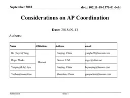
Date 20180913 Authors Name Affiliations Address email Bo Boyce Yang Huawei Nanjing China yangbo59huaweicom Roger Marks Denver USA rogerethairnet Yunping Lily Lyu ID: 720080

2018 mimo slide coordination mimo 2018 coordination slide distributed bss sta information transmission september joint 802 handover type time

Share:

Link:

Embed:

Download Presentation from below link

Download Presentation The PPT/PDF document "September 2018 Slide 1 Considerations o..." is the property of its rightful owner. Permission is granted to download and print the materials on this web site for personal, non-commercial use only, and to display it on your personal computer provided you do not modify the materials and that you retain all copyright notices contained in the materials. By downloading content from our website, you accept the terms of this agreement.


Presentation Transcript

Slide1

September 2018

Slide 1

Considerations on AP Coordination

Date: 2018-09-13

Authors:

Name

Affiliations

Address

email

Bo

(Boyce) Yang

Huawei

Nanjing, China

yangbo59@huawei.com

Roger Marks

Denver, USA

roger@ethair.net

Yunping

(Lily)

Lyu

Nanjing, China

lvyunping@huawei.com

Yuchen

(Jason) Guo

Shenzhen, China

guoyuchen@huawei.comSlide2

Introduction

AP coordination has been suggested in several EHT TIG contributions ([1]-[5]) with the goals of improving throughput in typical scenarios.

AP coordination would be a major feature differentiating EHT from 802.11ax.AP coordination comes in many possible forms. In general, the technologies can be classified into two types:MAC coordinationPHY coordination

Slide 2September 2018Slide3

September 2018

Slide 3

MAC Coordination

MAC-level control information exchangeAPs exchange MAC-level control informationFrame-level time synchronization

Frame synchronization, can be achieved by coordinating trigger frames without additional hardware.Tolerance of ~0.8 µsec or better may be required in some scenarios

Candidate approaches

transmission coordination

Non-Coherent

Joint Transmission

handover

coordination

interference nullingSlide4

September 2018

Slide 4

Transmission Coordination

AP 1

AP 2

AP 3

avoid inter-BSS interference and collisions

enhances spatial reuse for distant APs

time slot

BSS ID

BSS 1 downlink

BSS 1

BSS 2

BSS 3

BSS 1 uplink

BSS 3 downlink

BSS 3 uplink

BSS 2 downlink

BSS 2 uplinkSlide5

Non-Coherent Joint Transmission

AP1 and AP2 can transmit the same data frame, without precoding, to

edge user to improve the signal qualitySlide 5

September 2018

AP 1

STA 1

AP 2

Data sharing

AP1 shares STA1’s data frame to AP2 beforehand

AP2 transmits the same data frame to STA1 at the same timeSlide6

September 2018

Slide 6

Handover Coordination

AP 1

STA 1

AP 2

Coordination between home AP and target AP can speed handover

Improves performance in, for example, warehouse and office scenarios

Example exchange:

Home AP and target AP exchange signal strength information

Target AP sends handover information to home AP

Home AP sends Target AP handover information to STA

STA uses Target AP handover information for speedy association

moving towards AP 2Slide7

September 2018

Slide 7

Interference Nulling

AP gathers CSI information from unassociated clients and then pre-codes to null signal there.Downlink throughput can be improved significantly in typical scenarios.

PHY technique, but does not necessarily require PHY information exchange between APs .

AP 1

STA 1

AP 2

STA 2

mutual nulling

CSI from AP 2 to STA 1 is need to null interference for STA 1

CSI from AP 1 to STA 2 is need to null interference for STA 2Slide8

September 2018

Slide 8

PHY Coordination

APs share data as well as control information.Joint precoding (spatial mapping) codes data for every stream in the joint transmission.Channel information exchange may be required, depending on precoding type,

Data could be shared by wired or wireless link.Strict synchronization requirementTransmission time must be precisely synchronized (may require nanosecond-level time synchronization).

Carrier frequency offset and Sampling Frequency Offset must be compensated precisely.

Phase synchronization is also needed for joint channel estimation and joint transmission.

Candidate technology

Distributed MIMOSlide9

Distributed MIMO

Slide

9Septembew 2018

Distributed MIMO (D-MIMO) coordinates a variable number of transmitters to improve throughput in typical scenarios.flexible number of spatial streams; for example, from 1 to 16higher spectral efficiency than collocated MIMO (C-MIMO)

D-MIMO could be a signature differentiated feature in EHT, as is MU-MIMO in VHT and OFDMA in HE

Note: the 3-tuple (M, L, N) means

( number of

sta

, number of antennas per AP, number of AP )

Figure 2 [6]

Figure 1Slide10

Distributed MIMO requirements

Slide

10September 2018

Distributed MIMO requires time, frequency and phase synchronizationDistributed transmitters need to transmit their signal simultaneously while maintaining CSMA compliance.

A possible approach is to specify a Joint Transmission Trigger frame used to trigger simultaneous transmission from distributed APs and sent after one transmitter obtains a channel access opportunity.Carrier and sampling frequency of distributed transmitters must be synchronized accurately to avoid OFDM inter-symbol interference

Carrier frequency offset can be measured when receiving the Joint Transmission Trigger frame, then the CFO can be compensated in the baseband.

Distributed transmitters can also synchronize their reference clock over the backhaul to synchronize the RF.

Phase synchronization is also needed as residual frequency error can lead to large phase drift in a long time interval. Slide11

Summary

Slide

11September 2018

We propose an overview of AP coordination candidate technologiesMAC coordination is easier to achievePHY coordination provides more opportunities to enhance performance.Slide12

References

[1] “Distributed MU-MIMO and HARQ Support for EHT” (802.11-18-1116-00-0eht)[2] “Multi-AP Enhancement and Multi-Band Operations” (802.11-18-1155-01-0eht)

[3] “EHT Technology Candidate Discussions” (802.11-18-1161-00-0eht)[4] “Discussion on EHT Study Group Formation” (802.11-18-1180-00-0eht)[5] “Extremely High Throughput (EHT) 802.11 – Study Group Creation” (802.11-18-1271-00-0eht)

[6] “Spectral efficiency of distributed MIMO systems”[J]. IEEE Journal on Selected Areas in Communications, 2013, 31(10): 2112-2127.Slide 12September 2018Slide13

Appendix:

Distributed MIMO Architecture

Slide 13

September 2018Slide14

Distributed MIMO Architecture

Slide

14Septemeber 2018

A single architectural AP, divided internally into a central AP-C and remote AP-Rs.Connectivity could be by Ethernet.AP-Rs are tightly synchronized and coordinated.

One coordinated MU-MIMO beamforming system.No handover.Slide15

Distributed MIMO Architecture: variations

Slide

15

September 2018

Variations of the distributed MIMO architecture, from one extreme to another:Type 1

: AP-R is simply antenna plus amplifier, connected with RF cable.

Type 2

: AP-R contains lower PHY and analog RF. AP-C contains MAC layer functions and upper PHY. Various splits between upper and lower PHY are possible.

Type 3

: AP-C is a TSN-based Ethernet switch. AP-R is a full AP with D-MIMO capabilities.

Type 1

Type 2

Type 3