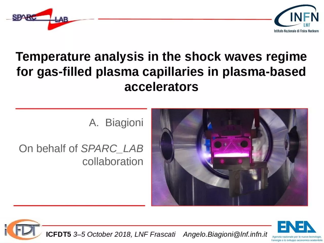
/
Temperature  analysis in the shock waves regime for gas-filled plasma capillaries in plasma-based Temperature  analysis in the shock waves regime for gas-filled plasma capillaries in plasma-based

Temperature analysis in the shock waves regime for gas-filled plasma capillaries in plasma-based - PowerPoint Presentation

hadley
hadley . @hadley
Follow
65 views
Uploaded On 2024-01-29

Temperature analysis in the shock waves regime for gas-filled plasma capillaries in plasma-based - PPT Presentation

Biagioni On behalf of SPARCLAB collaboration ICFDT5 35 October 2018 LNF Frascati AngeloBiagionilnfinfnit Outline ICFDT5 35 October 2018 LNF Frascati AngeloBiagionilnfinfnit ID: 1041429

plasma capillary regime gas capillary plasma gas regime temperature lnf pressure properties length shock infn biagioni angelo beam density

Share:

Link:

Embed:

Download Presentation from below link

Download Presentation The PPT/PDF document "Temperature analysis in the shock waves..." is the property of its rightful owner. Permission is granted to download and print the materials on this web site for personal, non-commercial use only, and to display it on your personal computer provided you do not modify the materials and that you retain all copyright notices contained in the materials. By downloading content from our website, you accept the terms of this agreement.


Presentation Transcript

1. Temperature analysis in the shock waves regime for gas-filled plasma capillaries in plasma-based acceleratorsBiagioniOn behalf of SPARC_LABcollaborationICFDT5 3–5 October 2018, LNF Frascati Angelo.Biagioni@lnf.infn.it

2. OutlineICFDT5 3–5 October 2018, LNF Frascati Angelo.Biagioni@lnf.infn.itMotivationsPlasma discharge capillaries as accelerating and focusing modulesGas-filled capillary plasma sourceExperimental set-upEffect on electron beam parametersShock Wave method to measure plasma propertiesConclusions

3. Plasma discharge capillary applicationsAngelo.Biagioni@lnf.infn.itne = 1016-1018 cm-3V = 15-20 kVImax = 240 AR = 500 μmL = 1-3 cmPWFAPlasma lens90 μm 25 μm Focusing (Compactness)Bφ > 500 T/m

4. Angelo.Biagioni@lnf.infn.itEmittance: we observe a stronger emittance growth during the plasma supersonic expansions until the plume density and the bunch density are comparable (plasma plume properties: pressure, temperature and density)Temperature: the plasma temperature inside the capillary affects the magnetic field along the radius and so the electron beam focusingPlasma lens theoretical model,courtesy of R. PompiliTransverse emittance (μm)CapillaryLongitudinal coordinate Z (cm)Stronger emittancegrowthSimulations by Architect,courtesy of V. ShpakovPlamsa plumesenx = 0.9 μmeny = 1.15 μmenx = 1.4 μmeny = 1.6 μmMotivations: Emittance Growth in Plasma Lenses

5. ICFDT5 3–5 October 2018, LNF Frascati Angelo.Biagioni@lnf.infn.itElectrodesGasoutflowMeasured current pulseI=240 AV=20 kVPlasma-discharge capillaries

6. 20 images separated by 100 ns, so 2 µs of total observation time of the plasma plumesThe ICCD camera area is 1024 x 256 pixel Plasma plumesDischarge voltage 18 kVCapillaryElectrodePlasma channel20 mm/2 μsBoth plama plumes can reach a total expansion length around 40 mm (20 mm each one) that is comparable with the channel length of 30 mm, so they can strongly affect the beam properties that passes through the capillaryTemperature, pressure and plasma density, inside and outside the gas-filled capillary plasma source, represent essential parameters that have to be investigated to understand the plasma evolution and how it can affect the electron beam.Vacuum Angelo.Biagioni@lnf.infn.it

7. Shock regime in different capillary geometries One inlet is placed in the center of the capillary Inlet Ø = 0.5 mmPlasma channel length = 10 mmPlasma channel Ø = 1 mmTwo inlets are placed at 2/3 of the plasma channel lengthInlets Ø = 0.3 mm Plasma channel length = 30 mmPlasma channel Ø = 1 mmIt has been studied how different geometrical properties can affect the termodynamc properties of the plasma (mixture of plasma, ions and neutral gas) and so the beam dynamics within the capillaryBoth capillaries: Voltage discharge: 18 kV Opening time of the electrovalve: 3 ms (frequency 1 Hz) H2H2Gas expansions will be different inside of two capillaries(Turbulence, density, pressure, temperature…)

8. Free-jet shock structureM<1Zone of silence (M>1)MackdiskCapillaryH2 gas inletsstreamlineBackground pressure (vacuum)Jet boundaryIn the shock regime formation, the outflow velocity u will increase because the thermal energy of the gas inside capillary is converted in kinetic energy when it goes into vacuum (adiabatic),The gas temperature decreases and therefore the characteristic sound speed will decrease along the plume axis.The shock wave creation has to be described by using the Mach number M=u/c, so this parameter will increase while the plasma plume expands.M=1

9. Shock regime analysisThe outflow velocity u will increase because the thermal energy of the gas inside capillary is converted in kinetic energy when it goes into vacuum (adiabatic)The gas temperature decreases and therefore the characteristic sound speed will decrease along the plume axis.ɣH2 = 7/5 Angelo.Biagioni@lnf.infn.it18 kV18 kV18 kV

10. Shock regime analysisF. Saint-Laurent et al, Fusion Engineering and Design 89 (2014) 3022–3038 Alexander Naß and Erhard Steffens, NIMA, 598 (3), 2009 653-666Stark broadening

11. Discussion of results (I) u∞ = 15 km/sT0 = 0.7 eVcorifice = 4.6 km/sccapillary = 6.9 km/sLplume = 11 mmu∞ = 21 km/sT0 = 1.4 eVcorifice = 5 km/sccapillary = 9.4 km/sLplume = 20 mmShort capillary (1cmx1mm)Long capillary (3cmx1mm)Different geometric properties of the capillary and the gas inside lead to different properties of the shock regime produced at the exits of the capillary itselfBy analysing the plume’s thermodynamic properties it is possible to get important informations about how the capillary could affect the beam dynamics Plasma lens results:et = 0.8 μmσ ≈ 100x100 μmet = 1.4 μmσ = 22x24 μmPlasma lens results:et= 0.8 μmσ ≈ 100x100 μmet = 1 μmσ = 18x20 μm

12. Discussion of results (II)T0 = 0.7 eVTplume = 0.32 -0.2 eVM = 1.7 – 3.5 (max 4.1)pcapillary = 60 mbarpplume = 4 - 1 mbar T0 = 1.4 eVTplume = 0.37 – 0.2 eVM = 0.9 – 3.3pcapillary = 150 mbarpplume = 2.5 - 1 mbar Inside capillary we can suppose a sonic regime (Ma ≈ 1): the higher is the temp T0, the higher is pressure pcapillaryOutside capillary there is a supersonic regime (1<Ma<5) but will be different between two capillaries: Lplume, ΔTplume, ΔpplumeThe turbolent regime inside capillary plays a crucial role for the thermodynamic properties f fluid motion characterized by chaotic changes in pressure and flow velocityShort capillary (1cmx1mm)Long capillary (3cmx1mm)

13. Long capillary (3cmx1mm)Discussion of results (III) Different current Ip inside the capillary will produce different temperature values that can be detected by using the shock regime at the ends of the capillaryIp = 100 A, T0 = 0.5 eVIp = 150 A, T0 = 0.85 eVIp = 185 A, T0 = 1.1 eVIp = 225 A, T0 = 1.4 eV

14. ConclusionsThe plasma confinement for plasma-based accelerators by mean of gas-filled capillary represents a good solution but several parameters have to be monitored to preserve the beam qualityThermodynamic properties, as temperature, pressure, density, particles velocities and gas turbulence, can evolve at different regime inside and outside the capillary, which in turn affect the beam dnamicsBy analyzing plasma plumes coming out from the orifices we have obtained the following results:This thermodynamic properties assume a crucial role for the LWFA, because the laser will be affected by temperature, speed and pressure changing both at entrance and exit of the capillary An accurate study of the turbulent regime inside the capillary should be made to understand how the plasma properties can evolveT0 in the capillaries, close to the ends and on axis, is 0.8-1.4 eV The temperature T outside the capillary shows an exponential decay Also the pressure p outside the capillary decreases exponentially with the distance from orificeThe pressure in the capillary p0 depends on the capillary shape (50-160 mbar) and accords with the sound speed inside capillary (6.9 km/s – 9.4 km/s) Angelo.Biagioni@lnf.infn.it

15. Thank youfor your attentionICFDT5 3–5 October 2018, LNF Frascati Angelo.Biagioni@lnf.infn.it

16. Limits of applicability: Knudsen numberThe Knudsen number (Kn) is defined as the ratio of the molecular mean free path length (λ) to a representative physical length scale. This length scale could be, in our case, the capillary length (L)Viscous fluid, Kn < 0,01Molecular fluid, Kn > 1Transition regime, 0,01 < Kn < 1Kn defines our flow regime: In fluid dynamics, the Knudsen number is used to define the limits of applicability of the continuum mechanics to the fluids and so the applicability of the Navier-Stokes equationsIf Kn < 0.01, we can apply the previous theory to our gas expansion, considering it as a continuum fluid (we can use N-S eqs, that is continuity equation, first and second laws of thermodynamics)In the zone of silence:In our region of interest, the zone of silence, the Knudsen number is always < 0.01Longer capillaryShorter capillary

17. On axis-symmetric free-jet gas expansionsA free-jet atomic or molecular flow can be produced by a supersonic gas expansion from a high-pressure gas source into a low pressure background, for this regime:If , the flow will exit supersonically (G≤2.05, for all gases)the flow parameters in the zone of silence are independent of boundary conditions (walls, pb), which is caused by the fact that information propagates at the speed of sound, whereas the gas moves faster

18. Temperature by using Stark effectSo far, we were not able to obtain the plasma temperature because we were not ableto measure the line intensitiesPlasma density determination using Stark broadening of spectral lines is a well established and reliable technique in the range of number density1014–1018 cm-3The electron temperature is an equally important plasma parameter which can be determined spectroscopically from the ratio of integrated line intensitieswhere ε(λ) is the emissivity, α(λ) is the absorption coefficient in cm−1, and L is the plasma length along the line of sight to the observerWhen we want to measure a temperature, the system should be in a thermodynamicequilibrium; since it is rarely complete, we can consider a useful approximation, local thermodynamic equilibrium (LTE):