/
SCOTCH STEERING MECHANISM SCOTCH STEERING MECHANISM

SCOTCH STEERING MECHANISM - PowerPoint Presentation

isla
isla . @isla
Follow
66 views
Uploaded On 2023-09-21

SCOTCH STEERING MECHANISM - PPT Presentation

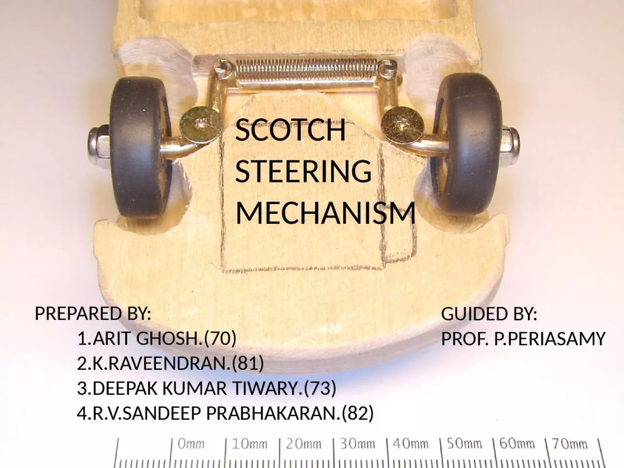
PREPARED BY 1ARIT GHOSH70 2KRAVEENDRAN81 3DEEPAK KUMAR TIWARY 73 4RVSANDEEP PRABHAKARAN82 GUIDED BY PROF PPERIASAMY ABSTRACT   ID: 1019094

wheel steering arm angle steering wheel angle arm design motion front mechanism system rack power action shaft pinion rear

Share:

Link:

Embed:

Download Presentation from below link

Download Presentation The PPT/PDF document "SCOTCH STEERING MECHANISM" is the property of its rightful owner. Permission is granted to download and print the materials on this web site for personal, non-commercial use only, and to display it on your personal computer provided you do not modify the materials and that you retain all copyright notices contained in the materials. By downloading content from our website, you accept the terms of this agreement.


Presentation Transcript

1. SCOTCH STEERING MECHANISMPREPARED BY: 1.ARIT GHOSH.(70) 2.K.RAVEENDRAN.(81) 3.DEEPAK KUMAR TIWARY.(73) 4.R.V.SANDEEP PRABHAKARAN.(82)GUIDED BY:PROF. P.PERIASAMY

2. ABSTRACT The project has been undertaken to modify the design of the steering system using a scotch yoke mechanism.This, mechanism consists of one fixed link, crank and a sliding link. By applying above concept we are going to prove Ackerman’s principle.  Finally we designed a new steering mechanism instead of available steering mechanism in market like power, linkage and rack and pinion.

3. Steering SystemFunction of Steering SystemControl of front wheel (sometimes rear wheel) direction.Maintain correct amount of effort needed to turn the wheels.Transmit road feel (slight steering wheel pull caused by the road surface) to the drivers hand.Absorb most of the shock going to the steering wheel as the tire hits holes and bumps in the road.Allow for suspension action.

4. Available Steering Systems:1.Linkage Steering System (Worm Gear)

5. 2.Basic Rack-and-Pinion SteeringPinion Gear- rotated by the steering wheel and steering shaft; it’s teeth mesh with the teeth on the rack.Rack- long steel bar with teeth along one section; slides sideways as the pinion gear turns.

6. 3.Power Steering normally use an engine driven pump and a hydraulic system to assist steering action. Three major types of power steering systems:Integral-piston linkage system.External power steering system.Rack-and-pinion systemIntegral power piston.External power piston.Integral Rack-and-pinion system is the most common.

7. Idea!!!

8. HOW! IF SCOTCH YOKE MECHANISM CAN BE ADOPTED IN A STEERING ACTION.

9. our aim is to convert circular motion into reciprocating motionso,

10. Using above mechanism we are going to prove the Ackermann steering principle……..

11. Scotch yoke The Scotch yoke is a mechanism for converting the linear motion of a slider into rotational motion or vice-versa. The piston or other reciprocating part is directly coupled to a sliding yoke with a slot that engages a pin on the rotating part. The shape of the motion of the piston is a pure sine wave over time given a constant rotational speed.

12. Wheel Alignment Requirement: CASTERCaster is the forward or backward tilt of the steering axis when compared with a true vertical line. 2.CAMBERCamber is the inward or outward tilt of the wheel when compared with a true vertical line.3.TOEToe is the difference between the front and rear edges of a set of tires. When the wheels are parallel to each other, toe is zero.4.King-pin inclination: It is the angle between vertical line to the king pin axis.The inclination tends to keep wheels straight ahead and make the wheels toget return to the straight position after completion of a turn.

13.

14. 1.Caster Angle : 5.5degree.2.Camber Angle: 2degrees.3.Kinpin Angle : 6degrees4.Toe in mm : 4mm.Wheel Alignment considerations for our design are:

15. Complete Alignment :

16. Component Description

17. PLATE:1.Connected to the steering wheel via splined steering rod and knuckle joint.2.Give complete rotary motion in action.3.Diameter of the plate = Total steering displacement on each side.Material Used: Aluminum.

18. Tie Rod:1.To transmit straight line motion In action.Material used: mild steel.Tie length = W + 2Lsin(φ)(where W = spindle-to-spindle centre distance, in.; Tie length = tie-rod length, in.; L = centre-to-centre lever arm length, in.; and = angle between lever arm and vehicle centreline, degrees. Estimate this angular value to begin the calculations.)

19. Pitman ArmThe Pitman arm is attached at one end to the steering gear's sectorshaft. The other end is connected to the centerlink (sometimesreferred to as a relay rod or draglink). The Pitman arm is the lever that converts the rotary motion of the sector shaft into side-to-side(lateral) motion. The Pitman arm is securely attached to the sectorshaft by splines, so that any movement of the sector shaft istransmitted to the Pitman arm and center link.Material used: cast iron.

20. Front axel:

21. ASSEMBLY DESIGN

22. Front view:

23. Bottom view:

24. During Steering Action:

25. CALCULATIONCross Arm AngleTan α =  Design Consideration,c = 1220 mm­­­ (i.e. Distance between the pivot of front axles)b = 2430 mm (wheel base)tan α=c/2btan α = Therefore,Cross arm angle “α” = 14.1˚ 

26. TO FIND TURNING RADIUSAt maximum lock angle of 45˚From design consideration,We obtain,Ɵ = 45˚ (i.e. angle formed by right wheel centerline with the rear axle)Ø = 37˚ (i.e. the angle formed by left wheel centerline with the rear axle axis)To find:The Turning Radius at Maximum lock angleƟL = tan-1 ( MR-12W )W = spindle to spindle distance or front axle lengthM = Distance between front axle to rear axle45˚ = tan-1 ( 2430R-( 12 X 1220 ) )Therefore,R = 3040 mm So, Turning Radius = 3040 mmTurning Radius from design considerations found to be 3040 mm. 

27. 10.2For Correct Steering Verification cot Ø - cos Ɵ = Ø = 37˚Ɵ = 45˚ cot 37˚ - cos 45˚ =  0.619 =   value lies between the 0.4 to 0.63 Therefore, [our value lies between the required range of ratio] 

28. CONCLUSION :As the DESIGN PROCEDURES is verified using Ackerman's calculation and pro-e tool, thereby we can say that our STEERING DESIGN is perfect.

29. FABRICATION PROCEDURE Plate is taken of required dimension.Facing, turning and required drilling done.Type equation here.Flat plate strip is cut and welded in the form of template.A small projection pin is inserted in to the plate.Two shat of required dimension is welded on to the template surface.Template is inserted in to the projected pin by taping and then bolted with the projection thread.Steering wheel is welded with a hollow shaft and another end of shaft is welded with nut.Then the system is fitted on a base frame.The template’s bold is fixed with nut of the steering wheel shaft.         

30. SL NO DESCRIPTION QNTY AMOUNT1.CIRCULAR PLATE12002.½”DIA.C.I PIPE15M4003.WHEEL HUB212004.STEERING COLUMN 15005.MACHINING EXPANCE 10006.EXTRA EXPANCE5007.TOTALRS 3800COST ESTIMATION:

31. THANK YOU