/
 Analog Applications Journal When good grounds turn badisolate Texas Instruments  Analog Applications Journal When good grounds turn badisolate Texas Instruments

Analog Applications Journal When good grounds turn badisolate Texas Instruments - PDF document

jane-oiler
jane-oiler . @jane-oiler
Follow
429 views
Uploaded On 2014-10-07

Analog Applications Journal When good grounds turn badisolate Texas Instruments - PPT Presentation

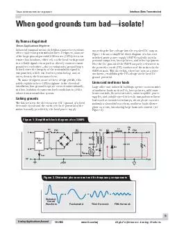
ticomaaj HighPerformance Analog Products Industrial communication via fieldbustransceiver systems often requires long transmission lines Designers unaware of the large groundpotential differences GPDs between remote bus locations either rely on the l ID: 3539

ticomaaj HighPerformance Analog Products Industrial

Share:

Link:

Embed:

Download Presentation from below link

Download Pdf The PPT/PDF document " Analog Applications Journal When good g..." is the property of its rightful owner. Permission is granted to download and print the materials on this web site for personal, non-commercial use only, and to display it on your personal computer provided you do not modify the materials and that you retain all copyright notices contained in the materials. By downloading content from our website, you accept the terms of this agreement.


Presentation Transcript

Texas Instruments Incorporated To make designers aware of these design pitfalls, thisinstallation, how ground loops are created unintentionally, C1C2 conductor, establishing the PE voltage as the local DC FundamentalWaveformThirdHarmonicFifthHarmonic =++ Figure 2. Distorted phase current and its frequency components Texas Instruments Incorporated 12Analog Applications Journal www.ti.com/aaj3Q 2008tal60-Hz line frequency make up the lion’s share ofFor nonlinear loads, however, the individual currents) at the transformer. The letter “C”via one conductor, designated as “PEN.” The PEN LoadALoadALoadBLoadB PEN Figure 5. TN-C system (a) with typically higher GPDsthan TN-C-S system (b) (a) TN-C system LoadALoadALoadB LoadB NNPE (b) TN-C-S system (b)Total neutral current due to Phase1Phase2Phase3TotalNeutralFundamental Figure 4. Total neutral current consists mainly of third harmonics Texas Instruments Incorporated 13Analog Applications Journal however, are in the millivolts range or lower and are thusto operation from only one local supply. GPDs do becomeeach operating from a different supply.signal is within the receiver’s input common-as the Texas Instruments SN65HVD2x family, whose inputcommon-mode range stretches from –20 V to +25 V.ing regular maintenance work) are out of the designer’sextent that the receiver’s input common-mode range is ElectricalInstallationElectricalInstallationElectricalInstallationHighLoopCurrentLowLoopCurrentGroundLoopGroundLoop (b) High loop current(c)Reduced loop current yet highly sensitive torequiring an additional PE conductor. The TN-C method,however, has a major drawback. Because the split into PEPE conductor within the distribution panel. Additionally,the star connection of the system’s neutral and PE con-under normal operation. However, most nonlinear loadsductor. This amount, although small for one circuit, easily Texas Instruments Incorporated 14Analog Applications Journal www.ti.com/aaj3Q 2008To allow for a direct connection of remote grounds, theWithout a reference to ground, the bus transceiverswould be operating from a floating supply. Thus, currentwon’t destroy components connected to the bus, as theirHowever, where the transmission wires connect to PCBcomponents close to the connector. To suppress current 123 Figure 7. Example of resistance complexity of grounding paths LocalProcessingCircuitLocalProcessingCircuitSMPSSMPSVREGVREGXCVRXCVRL1L2N1N2PE1PE2SupplyIsolatorSignalIsolator23 Figure 8. Isolation of two remote transceiver stations with single-ground reference Texas Instruments Incorporated 15Analog Applications Journal tiald VCC3VCC2VCC4VCC1RRRRDDDDGND3GND2GND4GND1IsolatedXCVRIsolatedXCVRIsolatedXCVRNon-isolatedXCVR Figure 9. Isolation of multiple fieldbus-transceiver stations IMPORTANT NOTICE Texas Instruments Incorporated and its subsidiaries (TI) reservestandard warranty. Testing and other quality control techniques areused to the extent TI deems necessary to support this warranty.applications using TI components. To minimize the risksunder the patents or other intellectual property of the third party, or aTexas Instruments products and application solutions: TIWorldwide Technical Support InternetTI Semiconductor Product Information Center Home Pagesupport.ti.comTI Semiconductor KnowledgeBase Home Pagesupport.ti.com/sc/knowledgebase Phone+1(972) 644-5580Fax+1(972) 927-6377 Internet/Emailsupport.ti.com/sc/pic/americas.htmEuropean Free Call00800-ASK-TEXASInternational+49 (0) 8161 80 2121Russian Support+7 (4) 95 98 10 701The European Free Call (Toll Free) number is not active in all countries. If you havetechnical difficulty calling the free call number, please use the international number above.Fax+(49) (0) 8161 80 2045 International+81-3-3344-5317Domestic0120-81-0036Internationalsupport.ti.com/sc/pic/japan.htm Domesticwww.tij.co.jp/picInternational+886-2-23786800DomesticToll-Free NumberToll-Free NumberAustralia1-800-999-084Malaysia1-800-80-3973China800-820-8682New Zealand0800-446-934Hong Kong800-96-5941Philippines1-800-765-7404India+91-80-41381665 (Toll)Singapore800-886-1028Indonesia001-803-8861-1006Taiwan0800-006800Korea080-551-2804Thailand001-800-886-0010Fax+886-2-2378-6808Emailtiasia@ti.comInternetsupport.ti.com/sc/pic/asia.htmti-china@ti.com of similar import. Similarly, such statements herein that describethe company's products, business strategy, outlook, objectives,of operations. We disclaim any intention or obligation to updateTrademarks: Mailing Address: Texas InstrumentsDallas, Texas 75265 Texas Instruments Incorporated Telephony Video & Imaging www.ti.com/wireless SLYT