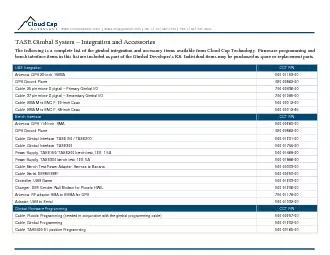
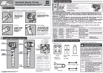
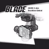
/
EN GB Axis Brushless Gimbal  EN WARNING Read the ENTIRE instruction manual to become familiar EN GB Axis Brushless Gimbal  EN WARNING Read the ENTIRE instruction manual to become familiar

EN GB Axis Brushless Gimbal EN WARNING Read the ENTIRE instruction manual to become familiar - PDF document

jane-oiler
jane-oiler . @jane-oiler
Follow
553 views
Uploaded On 2014-12-16

EN GB Axis Brushless Gimbal EN WARNING Read the ENTIRE instruction manual to become familiar - PPT Presentation

Failure to operate the product correctly can result in damage to the product personal property and cause serious injury This is a sophisticated hobby product It must be operated with caution and common sense and requires some basic mechanical abilit ID: 24642

Failure operate the

Share:

Link:

Embed:

Download Presentation from below link

Download Pdf The PPT/PDF document "EN GB Axis Brushless Gimbal EN WARNING ..." is the property of its rightful owner. Permission is granted to download and print the materials on this web site for personal, non-commercial use only, and to display it on your personal computer provided you do not modify the materials and that you retain all copyright notices contained in the materials. By downloading content from our website, you accept the terms of this agreement.


Presentation Transcript

1EN ® GB200 2-Axis Brushless Gimbal 2EN WARNING: Read the ENTIRE instruction manual to become familiar with the features of the product before operating. Failure to operate the product correctly can result in damage to the product, personal property and cause serious injury. This is a sophisticated hobby product. It must be operated with caution and common sense and requires some basic mechanical ability. Failure to operate this Product in a safe and responsible manner could result in injury or damage to the product or other property. This product is not intended for use by children without direct adult supervision. Do not use with incompatible components or alter this product in any way outside of the instruc-tions provided by Horizon Hobby, LLC. This manual contains instructions for safety, operation and maintenance. It is essential to read and follow all the instructions and warnings in the manual, prior to assembly, setup or use, in order to operate correctly and avoid damage or serious injury. The following terms are used throughout the product literature to indicate various levels of potential harm when operating this product:NOTICE: Procedures, which if not properly followed, create a possibility of physical property damage AND a little or no possibility of injury.CAUTION: Procedures, which if not properly followed, create the probability of physical property damage AND a possibility of serious injury.WARNING: Procedures, which if not properly followed, create the probability of property damage, collateral damage, and serious injury OR create a high probability of super“ cial injury. NOTICE All instructions, warranties and other collateral documents are subject to change at the sole discretion of Horizon Hobby, LLC. For up-to-date product literature, visit horizonhobby.com and click on the support tab for Age Recommendation: Not for children under 14 years. This is not a toy. € Always keep a safe distance in all directions around your model to avoid collisions or injury. This terference from many sources outside your control. Interference can cause momentary loss of control.€ Always operate your model in open spaces away from full-size vehicles, traf“ c and people.€ Always carefully follow the directions and warnings for this and any optional support equipment (chargers, rechargeable battery packs, etc.).€ Always keep all chemicals, small parts and any-€ Always avoid water exposure to all equipment not speci“ cally designed and protected for this purpose. Moisture causes damage to electronics.€ Never place any portion of the model in your mouth as it could cause serious injury or even death.€ Never operate your model with low transmitter batteries.€ Always keep the aircraft in sight and under control.€ Always move the throttle fully down at rotor strike.€ Always use fully charged batteries.€ Always keep the transmitter powered on while the aircraft is powered.€ Always remove batteries before disassembly€ Always keep moving parts clean.€ Always keep parts dry.€ Always let parts cool after use before touching.€ Always remove batteries after use.€ Never operate an aircraft with damaged wiring.€ Never touch moving parts. Safety Precautions and Warnings 4EN A. GB200 2-Axis Camera Gimbalw/CGO1 compatible mounting plateB. Assembled isolation mountC. (4) Mounting ScrewsD. Knurled 3mm screwE. 3-wire harness F. 2-wire power harness G. Alternate top mounting plateH. GoPro (3/3+) compatible camera mounting plateI. (3) 2-wire harnesses (not used)J. Small hex wrenchK. Large hex wrenchCopper foil RF shield (not shown) Table of Contents Box ContentsBox Contents ...........................................................4Connection Ports ......................................................5Installing the Isolation Mount ...................................6Routing the Wiring ...................................................7Changing the Camera Mount....................................8Installing the Gimbal ................................................9Mounting the Camera ............................................10Gimbal Modes ........................................................11Transmitter Programming ......................................11Using the Gimbal ...................................................12LED Codes .............................................................12Troubleshooting .....................................................13 ACDKJHBGEFI 5EN Connection Ports BCD EF E. Software Update PortF. Yuneec’ Receiver PortG. Spektrum’ Remote Receiver PortA. 5V Power PortB. Universal Input Port (C. Blade 350 QX2/AP Input PortD. Mode Control Port ( 6EN (version 1), you will need to change the pre-installed top mounting plate before attaching the isolation mount to your airframe. See the illustration at right.Using the large hex wrench provided, install the isolation mount with the 4 included screws. Do not overtighten. Carefully push the lower plate forward to access the front mounting plate hole. 350 QX2 and APFront Top Mounting Plate 7EN Routing the Wiring€ If you are installing the GB200 on a Blade 350 QX (version 1), use the included 2-wire harness (red and brown).€ If you are installing the GB200 on a Blade 350 QX2 or 350 QX2 AP, use the included 3-wire harness(red, brown and orange).1. Plug the servo connector into the ” ight control board as shown.2. Route the JST connector through the hole in the 2 8EN Changing the Camera Mountpre-installed. If you are using a GoProwith your gimbal, it is necessary to change the 1. Turn the camera mount on the gimbal until the set screw faces the notch in the gimbal arm. 2. Loosen the set screw using the small hex wrench included, as shown.3. Slide the camera mount away from the gimbal motor while carefully sliding the gyro plate from 4. Carefully remove the gyro board from the gyro plate. Double-stick tape “ rmly holds the board on the mount. 5. Install the gyro board in the alternate camera mount gyro plate. The plates are not 6. Wrap the gyro board wire harness loosely clockwise one whole turn around the end of the camera mount toward the gimbal motor.7. Slide the gyro plate onto the camera mount.8. Slide the camera mount onto the motor shaft, taking care to align the ” at on the motor shaft with the set screw on the mounting plate.9. Insert and tighten the set screw. 33 7896 3 mount 9EN On the original 350 QX quadcopter, the gimbal will automatically level without installation of an optional remote receiver. If transmitter control of the pitch axis is desired, connect a Spektrum Remote Receiver (SPM9645, sold separatelythe remote receiver to the upper gimbal body using double-stick tape. Bind the remote receiver while binding the quadcopter receiver to your transmitter. If the gimbal does not respond to the transmitter, pushing towards the rear of the plate as shown at left. To remove the gimbal, push in the restraining clip and correct port in the gimbal. See Connection PortsInput Port as shown at the left. Power Port. The gimbal will stabilize roll and pitch normally, but will have no transmitter control of the pitch axis. If you wish to have transmitter control of the pitch axis, a seperate remote receiver is requiredsee below 10EN Mounting the Camera 32 32 1. Slide the camera fully into the gimbal as shown.2. Install the 3mm screw through the mount and into the camera body as shown. 3. Insert the Wi-Fi antenna through the mount and into the camera body until it clicks. Rotate the 1. Install the included copper foil shield around the camera body using the included instructions.2. Slide the camera and shield fully into the gimbal as shown.3. Slide the rubber strap around the camera body and lens as shown.IMPORTANT: Consult local laws and ordinances before installing and operating any type of photograph-capable 11EN Gimbal Modes Transmitter ProgrammingAngle Mode (Green LED)Velocity Mode (Blue LED)€ The gimbal pitch angle corresponds directly to the € The gimbal will automatically stabilize in the € The gimbal pitch angle moves away from neutral in € The farther away from center the transmitter control input is, the faster the gimbal moves in the € The pitch angle movement is stopped by centering € The gimbal will automatically stabilize in the Transmitter control of the pitch angle of the GB200 is For the greatest control of the gimbal functions, an To program your transmitter:€ Set channel 7 to a dial, slider or lever for gimbal € Change channel 7 servo reversetravel direction you prefer.€ Set channel 8 to a 2-position switch to choose € Change channel 8 servo reverse for the switch direction you prefer.€ Angle Mode will be active if you use the signal € Velocity Mode will be active if you use only the power output from the 350 QX/2/AP in conjunction with a remote receiver.€ The DX7 uses a 2-position switch on channel 7. When using this transmitter, the gimbal will default to Angle Mode and will travel to either full up or full down, depending on the position of the channel 7 switch. You can adjust the endpoints in your 12EN LED Codes 1. Place the quadcopter on a ” at and stable surface. Ensure there are no obstructions in the path of the 2. Switch on your transmitter.3. Switch on your quadcopter. The GB200 will power on with the quadcopter. NOTICE: You must have a camera mounted to the GB200 for the gimbal to initialize properly.After the gimbal initializes, the LED will glow purple for approximately 3 seconds. In those 3 seconds, the camera mount may be rotated up or down by hand to your desired neutral pitch position. When the LED changes to green or blue, the neutral position is set and the GB200 is ready for use.The gimbal will now compensate for any roll and pitch movements encountered by your quadcopter.If desired, you may change the pitch angle of the gimbal at any time using your programmed GreenRedBluePurpleNo control(Power Only) 350 QX2/AP Port Connected Velocity ModeNo control(Power Only) 350 QX2/AP Port Connected Initialization CompleteNeutral Position Change AvailableNo Gyro Data 13EN Troubleshooting ProblemPossible CauseSolution The gimbal vibrates after switching ONLoose cameraSecure the camera in the mountswitching ONGimbal is not ONIncorrect gimbal connectionsCorrectly connect gimbalto control inputs. RED and Incorrect gimbal connectionsCorrectly connect gimbalLED ” ashes slowlyGimbal gyro board damageRepair or replace wiring or gyro boardAngle or Velocity ModeCorrectly connect gimbal, repair or 14EN Replacement Parts Exploded View Optional Parts #Part #Description BLH7904Gimbal Arms: GB200BLH7905Gimbal Motors: GB200BLH7906Gimbal Mount: GB200BLH7907Gimbal Control Board: GB200 #Part #Description BLH7908Camera mount CGO1: GB200Camera mount Go Pro Hero 3: GB200BLH7910GB200 Brushless Gimbal Part #Description SPM9645DSMX Remote Receiver 165422 15EN ©2014 Horizon Hobby, LLC.Blade and the Horizon Hobby logo are registered trademarks of Horizon Hobby, LLC.The Spektrum trademark is used with permission of Bachmann Industries, Inc. GOPRO is a registered trademark of Woodman Labs, Inc. in the United States and other countries. Yuneec and CGO1 are trademarks of Yuneec International Co., Ltd.All other trademarks, service marks or logos are property of their respective owners. Patents pending. Created 07/14 46284 BLH7910