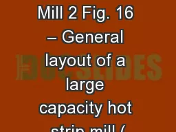
/
Hot Rolling Mill 2 Fig. 16 – General layout of a large capacity hot strip mill ( Hot Rolling Mill 2 Fig. 16 – General layout of a large capacity hot strip mill (

Hot Rolling Mill 2 Fig. 16 – General layout of a large capacity hot strip mill ( - PowerPoint Presentation

jane-oiler
jane-oiler . @jane-oiler
Follow
410 views
Uploaded On 2018-03-16

Hot Rolling Mill 2 Fig. 16 – General layout of a large capacity hot strip mill ( - PPT Presentation

Sollac Fos sur Mer Dofasco 2 Hot Strip Mill 3 Reheat Furnaces Rougher Finishing Mill Runout Table Coilers Slab 216 mm Transfer Bar 30 mm Strip 1216 mm thick 5081600 mm wide Advanced Hot Mills ID: 653435

strip mill cold figure mill strip figure cold line annealing roll entry rolling hot layout min furnace speed thickness

Share:

Link:

Embed:

Download Presentation from below link

Download Presentation The PPT/PDF document "Hot Rolling Mill 2 Fig. 16 – General l..." is the property of its rightful owner. Permission is granted to download and print the materials on this web site for personal, non-commercial use only, and to display it on your personal computer provided you do not modify the materials and that you retain all copyright notices contained in the materials. By downloading content from our website, you accept the terms of this agreement.


Presentation Transcript

Slide1
Slide2

Hot Rolling Mill

2

Fig. 16 – General layout of a large capacity hot strip mill (

Sollac

Fos sur Mer)Slide3

Dofasco #2 Hot Strip Mill

3

Reheat Furnaces

Rougher

Finishing Mill

Runout Table

Coilers

Slab

216 mm

Transfer Bar

~30 mm

Strip

1.2-16 mm thick

508-1600 mm wideSlide4

Advanced Hot Mills

4Slide5

Gallatin Steel (CSP)

5Slide6

Thin Strip Casting

6Slide7

Reheating Furnaces

7

Figure 3.8 Walking beam furnace at SSAB, Domnarvet.

Figure 3.9 Evaporative cooling system on walking-beam furnace at SSAB, Domnarvet.Slide8

Reheating Furnaces

8

Figure 3.7 Sketches illustrating operation of a walking-beam furnaceSlide9

Slab Reheating

9

Figure 3.5 Heating time as a function of slab thickness

Figure 3.6 Furnace heating capacity as a function of slab thicknessSlide10

Hot Mill Layout

10

Stand or Unit

Stand Type

Roll Sizes (in.)

Speed (fpm)

Drive Power (hp)

Remarks

Vertical edger

First rougher

2-hi

46

48 x 68

250

220

1500 ac

4500 ac

Back-passing

provision

hydraulic roll changing

Second rougher with 33 inch vertical edger

2-hi

48

x

68

220

4500 ac

Space available for future back passing

Third rougher

with 33 inch vertical edger

4-hi

42 & 56 x 68

330

8000 ac

Gear drive and pinion stand. Gear

type spindles and hydraulic roll changer

Fourth rougher

4-hi

42 & 56 x 68

330

dc drive for speed

Foundations only for future installation

Fifth rougher

Crop shear

Scale breaker

4-hi

42 & 56 x 68

658

250/500

8000 ac

Six finishing stands (F1-F6)

4-hi

28 & 56 x 683240 out of F67000 (each)Rapid work-roll changing electric loopers, AGCSeventh stand3740 out of F7Future installationTwo X-ray gages Width gage Runout tableTwo coilers500 eachAbout 500 ft long 3-blocker roll type

Table 3.3 Basic Data For 68-Inch Hot Strip

MillSlide11

Roll Stack

11

Bending system

Four-high millSlide12

Mill Stand

12

4 high mill system in Mae West designSlide13

Mill Housing

13Slide14

Mill Stand

14

Figure No. 3 Mill Stand ElevationSlide15

Strip Edge Drop

15

Edge drop compensation

Elastic deformation of roll assembly under rolling conditionSlide16

Strip Shape

16

Shape CalculationSlide17

CVC Crown Control

17

Continuously Variable Crown (CVC)Slide18

Pair Cross Mill

18

Figure 7.1 Construction of PC mill (Tsukamoto and Matsumoto)Slide19

Roll Bite Forces

19

Physical Forces within the Roll BiteSlide20

Sims Diagram

20Slide21

Cold Mill Layout

21

Typical layout and material flow of a cold rolling millSlide22

Pickling Line

22

Table 6.3 Design Characteristics of a Modern Pickling Line

DIMENSIONS

LINE SPEEDS

Strip thickness: 1 to 6

mm

Strip width 1000 to 1850 mm

Coil

OD maximum: 2200

mm

Coil ID entry: 620 to 850

mm

Coil ID exit: 600 mm

Coil

weight: 39 tons

Entry speed: 600 m/minSpeed in pickling: 220 m/minExit speed: 350 m/min

Acceleration time: 10 SecondsEmergency stop: 5 secondsLine length: 200 metersSlide23

Cold Rolling Mill

23

4-high reversing cold rolling and temper millSlide24

Tandem Cold Mill

24

Main equipment of tandem cold millSlide25

Gauge Control

25

Thickness control for tandem cold rolling millSlide26

Cleaning Line

26

Figure 23.1 Schematic arrangement of a typical electrolytic cleaning lineSlide27

Batch Annealing

27

Figure

23.29 Single-stack coil-annealing

furnace with base, fan, inner cover and fan coils with convectors (

Rao

et al.).

Figure

23.12 Time-temperature cyclesSlide28

AlN Precipitation During

Coiling

28

Role of AlN precipitation during subsequent annealing

:

Batch annealing

: AlN precipitation during annealing

preferred

Continuous annealing

: AlN precipitation during coiling preferredSlide29

Continuous Annealing

29Slide30

Continuous Annealing

30

Table 23.19 Fukuyama Works No. 1 Continuous Annealing Line*

Material

Thickness

Width

Entry and delivery coils

ID and OD

Weight

Line speed (cold rolled strip)

Entry section

Furnace section

Delivery section

Line speed (black plate for tinning)

Entry section Furnace section

Delivery section Capacity Cold rolled strip Black

plate for tinning

Cold rolled mild steel strip0.15 to 0.8 mm457 to 1067 mm508

x 2440 mm 32,000 kg max

188 m/min

150 m/min

188 m/min

572 m/min

457 m/min

572 m/min

24 tonnes/hr (0.6 mm

x

800 mm)

44 tonnes/hr (0.254 mm

x

813mm)

Table 23.20 Mechanical Properties, 0.8 mm Strip

Continuous annealing

Batch annealing

Yield stress (kg/mm

2

)

Tensile strength (kg/mm

2

)

Elongation (%)

Erichscn value (mm)

r-value

CCV, mm

22.0

32.9

45.0

10.1

1.51

37.8

22.2

32.046.510.41.2637.9Table 23.21 Properties of soft tinplate, 0.32 mm thick Continuous annealingBatch annealingYield stress (kg/mm2)Yield point elongation (%)Tensile strength (kg/mm2)Elongation (%)Erichscn value (mm)Hardness (hr 30T)ATC (µA/cm2)IYV (µg/3 in2)PLT (s)28.12.134.336.68.954.80.023.5333.05.436.437.09.355.00.077.75*Note: Capacity for cold sheet can be increased through additional heat input of the accelerated over-aging zone.Slide31

Microstructure Evolution During Cold

Rolling

31

Deformation

Work hardening

Ferrite (

a

) / PearliteSlide32

Microstructure Evolution During

Annealing

32

Preheat

Soaking

Cooling

Over-aging

Final Cooling

Recovery

Recrystallization

Grain growthSlide33

Temper Rolling

33

Figure

24.3 Yield strength variation with elongation

Figure

24.2 Stress-strain curves: (a) box-annealed rimmed deep-drawing steel; (b) diagram illustrating offset method for determining yield strengthSlide34

Temper Mill

34

Figure 24.10 Layout of temper and processing line (TPL) facility (Fujiwara et al.).Slide35

Tinning Line

35

Fig. 18 - Layout of an electrolytic tinning lineSlide36

Hot Dip Galvanizing

36

General characteristics

Material:

cold rolled mild steel strip

Entry YS 800 MPa maxi-200 MPa mini

Exit YS 140 MPa mini

Strip width:

Mini 750 mm

Maxi 1850 mm

Strip thickness:

Mini 0.30 mm Maxi 1.6 mm (2 mm with allowance)

Coil dimension Entry Exit

Line speed

Engagement 0 to 60 m/mm

Entry 20 to 200 m/mm (240)

Treatment 40 to 150 m/mm (180) Exit 20 to 200 m/mm (240)

Commissioned in 1991

Outside diameter mini 1200 mm mini 1200 mm maxi 2100 mm maxi 2100 mm

Inside diameter

610 mm 506-610 mm

Weight

31000 kg

31000 kg

Fig. 4 - Schematic layout of a hot dip galvanizing line