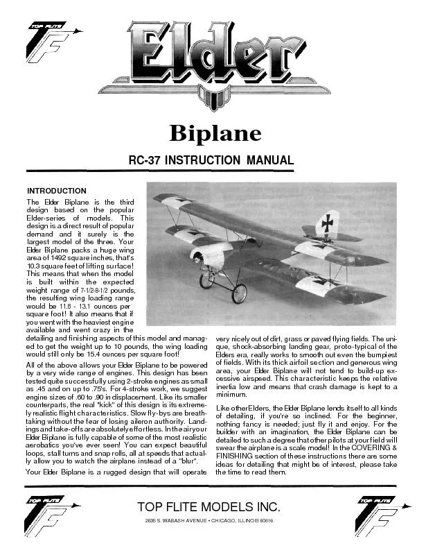
/
BiplaneRC-37 INSTRUCTION MANUALINTRODUCTIONThe Elde Biplane i the thir BiplaneRC-37 INSTRUCTION MANUALINTRODUCTIONThe Elde Biplane i the thir

BiplaneRC-37 INSTRUCTION MANUALINTRODUCTIONThe Elde Biplane i the thir - PDF document

karlyn-bohler
karlyn-bohler . @karlyn-bohler
Follow
421 views
Uploaded On 2016-05-04

BiplaneRC-37 INSTRUCTION MANUALINTRODUCTIONThe Elde Biplane i the thir - PPT Presentation

Earlier we touched on engine recommendations YourElde Biplane kit contain a highqualit fille nylon motormount tha wil work wit some of the engine suggestionsor thi design but not all If the engine ID: 305744

Earlier touched engine

Share:

Link:

Embed:

Download Presentation from below link

Download Pdf The PPT/PDF document "BiplaneRC-37 INSTRUCTION MANUALINTRODUCT..." is the property of its rightful owner. Permission is granted to download and print the materials on this web site for personal, non-commercial use only, and to display it on your personal computer provided you do not modify the materials and that you retain all copyright notices contained in the materials. By downloading content from our website, you accept the terms of this agreement.


Presentation Transcript

BiplaneRC-37 INSTRUCTION MANUALINTRODUCTIONThe Elde Biplane i the thirddesign based on the popularElder-series of models. Thisdesign is a direct result of populardemand and i surely is thelargest model of the three. YourElde Biplane packs a huge Earlier we touched on engine recommendations. YourElde Biplane kit contain a high-qualit fille nylon motormount tha wil work wit some of the engine suggestionsor thi design, but not all. If the engine choic fo yourElde Biplane wil not wor wit thi mount, i might bnecessary to visi your local retai hobby shop to obtainthe correct motor mount fo your engine.IMPORTANT NOTE:TOP FLITE MODELS, INC. Would certainl recommendthe Elde Biplane as a firs R/C powered aircraftHowever, if you are a beginner t the sport of R/C flyingwe would urge you t seek and use experienceassistanc in constructin and flyin thi airplane.Again i you are new t thi hobby, conside this:Flying thi or any othe radio-controlle model aircraf isa PRIVILEGE and not a RIGHT and thi privileg beginswit th utmos safet consideration t others andyoursel as well A R/C model airplan i inexperiencedhands has th potentia of doing serious personal or pro-perty damage. These safet consideration star at thebuilding board by followin instructions seeking com-peten help whe you are confuse and avoiding short-cuts These consideration have t b carrie overt theflyin fiel wher safet must come firs and limitationcannot b exceeded. We urge you to:1.Send fo and obtain you AM (Academy of ModelAeronautics membership whic wil provide insuranc fo your R/C activitie — D NOT RELY ONHOMEOWNERS INSURANCE.2 Join an AM sanctione R/C flyin club i your areawher you can obtai competent professiona instructio i trimming and learning how to fl thismodel.Check wit your favorit loca hobby shop fo the required AM forms o the address where they can b obtained.WARNING!!A radio controlle model is not a "toy." Care andcautio must b take i properly building themodel, as wel as in th installatio and use of theradio contro device. I is importan t follo alldirection as t the constructio of thi ki as welas installatio and use of the engine and radiogear. The advic and assistanc of a wel experienced builder and pilot is highly recommend-ed. Don't tak chances! Improper building, opera-tion, or flyin of thi model could result in seriousbodily injury to others, yourself or propertydamage.PRE-CONSTRUCTION NOTESThe Elde Biplane, like other Top Flit kits employs theuse of die-cu wood t ease the task of constructionparts fi and identification The dies used fo thi kithav bee rigorously checked for absolute accuracyand should provide you wit excellen fit Die-cut partsshould b carefull removed fro thei sheets by firslightl sanding the back of each sheet of parts and thencarefull removing each part. Use a ligh garnet paperfo the sanding and keep a sharp hobby knif wit anX-act #11 blade, or equivalent handy fo assistanc iremoving any part tha might not have completel cutthrough b the dies. Parts whic oppose one anotherand must b precisel uniform—suc as fuselag sides,ribs, etc.—shoul b carefull "matched afte theirremoval fro the part sheets. Matchin is the process ofholding the opposing pieces togethe wit eithe pins,tape or spot gluin and lightl sanding th edges of thepart unti the are identical A sanding block wit lightgarnet paper is most usefu fo thi and other phases ofconstruction.Your building surfac should b at least large enough taccommodat th win panels Thi surfac shoul ba absolutel fla as possibl and ye b able to acceppins easily We have foun tha a produc such asCelote fibe board work quit wel fo thi purpose.Anothergoo surfac can b foun i most well-stockehardwar stores-a 2'x4'fiberboar ceilin tile Theseare quit inexpensiv and can b used fo severalairplanes befor needin replacementA wit most R/C kit tha are constructe fro wood, aselectio of tools - mos of whic can b foun in thaverage workshop - ar a must t do th jo correctly• Hobby knif and sharp #11 blades• Single-edg razor blades•T-pin• Sanding block in assorte sizes• Sandpaper in variou grit• Hand-held hobby saw suc as an X-act• Dremel too or power dril and assorte dril bits• Straight-edge preferabl metal, at least 36 long• 90 triangl• Solderin iron, flu (silver) and solder• Carbide cut-of whee fo wir cuttin• Small powe jig-saw such as a Moto-Saw• Razor plane• Tapes, suc as masking and cellophanOur Elder were constructe usin a variet ofcommon hobby adhesives includin 5-minut epoxy,cyano-acrylates and 1-hour epoxy. Since al of us haveour own constructio technique and favoritadhesives, stic wit th ones you are familia wit andprefer However, in certai areas ther wil be callout focertai type of adhesives, and w urge you t tr not tsubstitut sinc doing so could possibly causeproblems structurallyThe last thin w should touc on befor w beginactua constructio is the sequence in whic the Elde iassembled. The sequence given t you i thi booklethas prove t b th most straight-forwar and providesthe finishe component i the order i whic you wilneed them t progress t th nex assembl phase. Tryto stic wit the buildin order presente here t avoidmistakes.2 Spread the plan out on your wor surface cove themwit a clea plasti material, suc as th backin froa roll of MonoKote or plasti wra and commenceconstructionUPPER WING ASSEMBLYWin constructio fo you Elde Biplane consist ofbuildin thre separat piece fo eac wing the twpanels and th cente section Note tha th upperwinpanels wil be joine t th upper cente sectio in thfollowin sequence without th top, inboard endssheeted. Thi sheetin wil b done in th FINALASSEMBL sectio o th manual. I thi and othebuildin sequences b certai tha yo are workin on aflat wor surface Carefull joi th plans fo th TOPLEFT WING and th TOP RIGHT WING, Plan Sheets 5and 6 at th cente line provided and accuratel securwit tape Thi provide th ful win plan on whic towork The win wil be buil directl ove th plans, socove the wit MonoKot backin or clea foo wrap.1 Start wit th cente sectio first Locate th die-cutsheet containin part W-11 (2, ply) W-12 (2 ply).W-13 (1, balsa), 4W- A' and 4 W-1 B's. Remov thesparts fro thei sheets and clean u any roughedges befor assembl2 Using th plans as a guide; measure, cut and butt-glue1/4"x1-1/2"lowe leadin edge,3/32"balsasheet and th x 1 trailin edge tha makes upthe botto of th cente section Note graindirectio o thes pieces Measure, cu and glu iplace the 3/8" x 1/2" upper leading edge. Glue one ofth W-11 pl dihedra brace in place agains theinside surfac of th leadin edge—b sur tha it'centered Glu th oute W-1 half-rib in placeagains th rear fac of th dihedra brace, lined-uwit th edges o th botto sheetin at righ anglest you wor surface Now glu th tw remainingW-1A' i place, using th "tick mark location onthe plan.3 A shown, the main dihedral brace syste is acomposit made by laminatin th tw W-12's (ply)to each side of W-13, whic result i a 1/4" thickpart—d thi now. Glu th complete dihedralbrac in plac t th botto sheetin and up againsthe rear edges of th fourW-IA's Be sure thi part icentered4 From your kit box, locate a piece of 1/4" x 1/2" sparstoc and cu tw 5 lengths Glue one of thesepiece in th to rear slot in th W-1 A' and againsth to forwar fac of th cente dihedra brace.Glue th othe on th bottom sheetin against thebottom rear fac o the dihedra brace.5 Now glu th fourW-1 rear half-rib i place behindthe mai dihedra brace. Glue th remainin W-11(ply) dihedra brac in place on th botto sheetinand against th rear edges o th fou W- B's. Locatethe 1/4" x 3/8" trailin edge materia in you ki boxand cu a 5" length Thi is now glue in placeagains th rear fac o the rear W-11 brace and tthe botto sheeting.3CAP STRIP AND3/32 x 1 TRAILINEDG NO SHOWTO WING CENTE SECTIO 6 Internally th cente sectio is done and all thatremains is th additio of th tosheeting—not grain. From th sheetin stocprovided cut fi and glu th sheetin in place.When dry, remove th cente sectio fro you worsurface Useyoursandin block tosmoot it'souteW-1A and W-1B side fo matin t the oute winpanels. The top, botto and leading edge can nowalso b sanded t shape. Set thi assembl aside fornow.7 I thi ste we want to prepare each of the requiredcomponents—th top and botto spars th 3/8" x1/2 fron L.E and th rear 1/4" x 3/8" T.E.—wit thproper dihedra angle at thei inboard ends. Thecross-sectio of th win tha is shown on th plansis ideal forthi purpose. Simpl lay, fo instance thebotto 1/4" x 1/2" balsa spar in plac ove thidrawing Note tha th outboar end is cu at 9degs.; but tha th inboard end must b cu at anangle t achiev th require 3/4" per panel dihedralangle. Make tw of thes botto spars Now repeatthis proces wit the to spars th leading edgesand th trailin edges (not tha lengt of thleading edges is develope fro th to vie of thwin plan). The inboard edges of thelower leading edges shoul b firs cu at 9 degs.and the slightl chamfere t match the neededdihedral angle.8 Star constructio b firslower leading edges in place, directl overth plans.Note tha th inboard edges of thes tw partterminat at th out edges o th tw outboardW-1A's Now pin th 3/32" x 1" botto trailin edgeplankin in place. Glue th 1/4" x 3/8" trailin edgesi plac on th top, rear of the3/32"trailin edgebottom sheet From you ki box locate tw 28"lengths of th tapere stock Noteon th plans tha th inboard ends of th taperedtrailin edges have been scallope t blend into thecente sections usin th plans as a guide, do thinow. Glue th tapere trailin edges in place—pisecurely From the3/32" x stoc provided,cut fi and glue each of th botto capstrip iplace—pi to secure. Using th 3/32 sheet balsaprovided, measure, cu and glue the inboard bottomwin sheetin in place—not grai direction.Locate th tw require W-6 wingtips clea theiredges and glue in place. The botto 1/4 x 1/2" spars(angled ends inboard) are now glued i place t thebottom win sheet and capstrips Now glu allrequired W-2A W-2B, W-3 and W-4 ribs in place,making sure the are vertica to the worksurface—D NOT glue W-3P's i place yet9 From your kit box locat th die-cu sheetcontainin the fou "ligh ply" W-3P win ribs. Boththe upper and lowe wing use tw of thes speciaribs fo attachmen of th interplan struts Notethat each of these ribs have indention on them folocation and placemen of th nylon mini horns,used fo attachment of the interplane struts On theupper wing the location of these horns is shown onthe lowe lef sid of plan sheet #5. Rout or cut aslot betwee the tw lowe set of fron and rearindention to allo th base of th mini horn t fitA long as you'r doing thi now, go ahead and cutthe slot require fo thes rib fo th bottowing—thes are th top fron and rear set ofindentions Onc th ribs have been properlyslotted plac th tw require fo th botto winback in you ki box fo late assembly The twappropriat W-3P rib fo th top win are ready foinstallation First, cut fi and glu in place th 3/32" x1/4 length of capstri stoc shown on the plans asfittin directl beneath each of the mini horlocations. Glue W-3P' in place.10 Locate and remov 1 W-5 rear angled ribs from theirdie-cu sheets Note on th plans tha th forwarends of thes rib are chamfere t fi agains theW-3 rib sheet and tha thei placemen does notinterfer wit th placemen of th top spar slots.Als note tha th innermos W-5 rib must btrimmed slightl so as not to interfer wit theplacement o th main dihedra brace GlueW-5' iplace. Glue al of th wingti brace (W-7, W-8, W-9,W-10, and W-15) in plac on th W-6 wingtips Notethat W-7, W-9 and W-10 need t have thei inboardends chamfere wit a sanding block to fi flus tothe oute fac of W-3.11 From you hardwood part bag, locat th fou 1/2" x5/8"" caban suppor blocks These are nowepoxie in plac as show on th plans, agains theinboard face o W-2A and W-2B and to the bottom3/32" botto cente win sheeting—w theuse of a 1-3 hour-typ epox fo thi step12 Now take th cente sectio whic wa assembledearlie and fi it to one of th win panels. Til it untithe tw arms of th W-11 ply dihedra brace fi flusto th fron and rear bottom sheetin and th centebrace assembl is correctl positione againstthe botto spar. Check thi fi t b sur allcomponent fi nicely Trim as needed t get properfit Prop and/o pin thi center sectio in thispositio as yo wil use it as a guide fo theremaining win panel parts Remember not to glueanything to the center section yet; it's only in placefor spacing purposes.13 Glue the fron 3/8" x 1/2" leading edge i plac on topof the lowe edge and agains thefron of each ful and hal rib (angle end inboard tfi agains tilte cente section) Glu th top 1/4" x1/2" spar in place (angled end inboard). Cut, fi andglue the 3/32 x V leading and trailin edge plankingi place—pi or tape t hold. Remove th centesectio fro th win panel and repeat the abovesteps on th remaining panel.14 Cut, fi and glue al top 3/32 x 1/4" capstrip in placeon al o the ribs and hal ribs.1 Remove the win panels fro the work surface.Inspect them fo any dried globs of glue, remove4 these wit a #1 X-act knife Tape or hold the tw 2win panels togethe wit th bottom of eachfacin th other—alig carefully Use you sandinblock to now shape th forwar wingtip identicallwit eac othe and the curve show on th plans.Wit th exceptio of th inboar ends, use yousandin block to carefull 'match th win panels,leadin edges, tip and trailin edges. Separat thpanel and use a sand ing block wit ligh paper oveal o th panel's surface t smoot them fo latercovering16 Firmly pin and/o weigh the cente sectio over yourprotecte wor surfac and epox th lef and righwin panels in plac t it, wit th tip o each panelsupported of th wor surfac by 3/4 t impar thcorrec dihedral Do not use so much adhesiv tha itdrip or runs but enoug t adequatel coat thepart required Usin a 1- hour typ epox wil giveyou plent o tim t positio all of the components 3Allo the structur to cureRemove the win fro your work surfac andinspect you work D any touch-u sanding or fillinas needed. The upper win is now complet wit theexceptio of the upper panel sheetin ove thehardwood blocks.Using th plans as a guide; measure, cu and butt-glu th leadin edge,shee and th 3/32 x 1" trailin edg tha make upth bottom o th cente section Note grai directio of thes pieces Measure cu and glu in placethe 3/8" x 1/2 upper leadin edge. Glu one of theW-11 pl dihedra brace in plac agains th insidsurfac of th leadin edge—b sur tha it'centered Glue the two outer W-1A' in plac againstth rear fac o th dihedra brace, lined-u wit thedges of th botto sheetin at righ angle t youwor surface Now glu tw W-1A' in plac jus inboard o th oute ones—not "tick marks onplans. The tw remainin W-1A' are now glue inplace at th cente o th structure spaced 1/4"apart to allo later dowel insertionA shown the main dihedral brace syste is a com-posit made by laminatin th tw W-12' (ply teach sid of the W-13, whic result in a 1/4" thicpart—d thi now. Glu th complete compositdihedra brac in plac t th botto sheetin andup agains th rear edges o the si W-1A's B surethis part i centered.LOWER WING ASSEMBLYThe lowe win fo th Elde Biplane i almost identical iconstuctio t tha of th uppe wing jus built Partnumbers and woo size are als th same. Howeverther are some differences primaril in th cente sectio structur and in part counts Carefull joi th plansfo the BOTTOM LEFT WING and the BOTTOM RIGHTWING, Plan Sheets 3 and 4, at the cente lines providedand accuratel secur wit tape Thi provide th fulwin plan on whic t work The lower wing lik th topwil be buil directl ove th plans, so cove the wit aMonoKote backin or clea foo wrap1 Star wit the cente sectio first Locat th die-cusheet containin part W-11 (2, ply), W-12 (2 ply),W-13(1, balsa), 6W-1A' and 4W-1B's Remove thesparts fro thei sheet and clean up any roughedges before assembly.4 From your kit box, locat a piec of 1/4" x 1/2" sparstoc and cu tw 5" lengths Glue one of thespiece in th to rea slot in th W-1A' and againsth to forwar fac o th cente dihedra brace.Glue th othe on th botto sheetin against thebottom rear fac of th dihedral brace.5 Now glu the fou W-1B rear half-rib in plac behindth main dihedra brace. Glue the remainin W-11(ply dihedra brac in plac on the botto sheetinand agains the rear edges o th fou W-1B's Locatthe 1/4 x 3/8 trailin edge materia in you ki boxand cu a 5" length. Thi is now glued in placeagains th rear fac of the rear W-11 brace and tothe botto sheeting.5 BOTTOM WING CENTER SECTION6 I thi step you are going t assemble the 5" lengto shaped hardwoo trailin edge stoc and thaileron torqu tube and wire t th win centesection Als locat and remov fro thei die-cusheets part W-14 and W-14B (due to th die-cu pro-cess yo have been provide wit tw set of thesparts you wil need onl one set). Pleas refe t thedetai drawin provide t understan th relationship of these parts.Start by glueing W-14A to the fron fac of thetapere hardwoo trailin edge piece Make sureW-14 is centere and tha th botto edge of thepar coincide wit th botto sur ace of th trai ingedge piece A shown th trailin edge must bnotche a littl t allo rea movemen o th threaded linkag arms. Do thi now wit eithe a rat-tai filor a Moto-Too and router bit. Note tha ther is aright and a left ailero driv assembly Hold one ofthes assemblie (i makes no differenc whic one)i plac t th edge/W-14 assembl in it'prope location Appl glu t th rear fac onl ofone o th tapere W-14B' (tapere end outboardand glu it in positio t th fron fac o th trailinedge, thu providin a "nest fo th ailero drivassembly Repea thi proces fo th opposit side.Remove th ailero driv assemblie and use asandin bloc t true-u eac sid o th trailinedge assembl (top and bottom and eac end. In-ser th tw ailero driv assemblie int thei ap-propriat "nests and hol thi entir assembl tth trailin edge of the win cente section Notetha yo now must slightl notc th centesection' 1/4" x 3/8" trailin edge t allo forwarmovement of th threade linkag arms—d thinow. Remov th tw ailero driv asemblie andusesandpapertorough-upthesurfaceofeachofthassemblies bras tubes Mi a smal amount o 1-hour epox and carefull glue only the torque rod6 tubes into thei appropriat locations—D NOTGET GLUE ON THE WIR TORQU ROD ARMSCarefull wip of any exces glue. Thi completeassembl can now be carefull glue directl t thtrailing edge of the cente sectio and allowe tdry.7 The cente section fro about the cente of W-13,back t th trailin edge can now be sheete wit3/32 balsa—not grai direction A th leadin edgeof the cente section cut, fi and glu in plac apiec o 3/32 x 1" leading edge sheeting For now,thi complete th cente section Yo wil add thlast piec o to sheetin afte the forwar winhold-dow dowe is installed8 I thi ste w wan t prepar eac of th requiredcomponents—th to and botto spars th 3/8" x1/2" fron L.E. and th rear 1/4" x 3/8" T.E.—wit thproper dihedra angl at thei inboar ends Thecross-sectio o th win tha is show on th planis idea forthi purpose Simpl lay fo instance thebottom 1/4-ing. Note tha th outboar end iscutat90degs. butthat th inboard end must be cu at an angl tachiev th require 3/4 per pane dihedra angleMake tw o thes botto spars Now repea thiproces wit th to spars th leadin edge andthe trai ing edge (not tha the lengt o th leadingedges is develope fro th to vie o th winplan). The inboarleadin edge shoul be firs cu at 90 degs. andthe slightl chamfere t match the neededdihedra angle.9 by firslower leading edges in place, directl overth plans.Note tha the inboard edges of thes tw part terminate at the outer edge of the tw outboardW-1A' in th cente section Now pin th 3/32" x 1"bottom trailin edge plankin in place. Glue th 1/4"x 3/8" trailin edges in place on th top, rear of the3/32"trailin edge sheet From the 3/32 x 1/4" x 36"stock provided, cut fi and glu each of th bottomcapstrip in place—pi t secure Using th 3/32"sheet balsa provided measure, cu and glue th in-board bottom win sheetin in place—not graidirection Locate th tw remaining W-6 wingtipsclean thei edges and glu in place. The botto 1/4"x 1/2" spar (angled ends inboard) are now glued inplace t th bottom win sheet and capstrips Nowglue all required W-2A, W-2B, W-3, W-3P and W-4 ribsi place, making sure they are vertica to the worsurface10 Locate and remove the remainin twelv W-5 rearangled ribs fro thei die-cu sheets Note on thplans tha the forwar ends of thes rib arechamfered to fi against th W-3 rib sides and thatheir placement does not interfer wit the place-ment of the top spar slots. Als note that the innermost W-5 rib must be trimme slightl so as not to in-terfer wit the placement of th main dihedralbrace. Glue W-5's i place. Glue all of the wingtibraces (W-7, W-8, W-9, W-10, and W-15) in place othe W-6 wingtips Not tha W-7, W-9 and W-10 needt have thei inboar ends chamfere wit a sandingblock to fi flus t the outer fac of W-3.11 Now tak the cente sectio whic wa asembledearlie and fi it t one o th win panels. Til it untith tw arms of th W-11 plydihedra brace fi flusto the fron and rear botto sheetin and th centebrace assembl is correctl positioned agains thbotto spar. Check thi fi to b sure all com-ponents fi nicely Trim i needed to get proper fitProp and/o pin thi cente sectio in thi positio asyou wil use it as a guide fo the remainin winpanel parts Remember not t glu anythin to thecente sectio yet it' only in plac fo spacing pur-poses.12 Glue the fron 3/8" x 1/2"" leading edge i place on topof the lower edge and againsfron of each ful and hal rib (angled end inboard tofi agains tilte cente section) Glu th top 1/4" x1/2" spa in plac (angle end inboard). Cut, fi andglue th 3/32 x 1 "leadin and trailin edge plankinin place—pi or tap t hold. Remove the centesectio fro th win panel and repea th abovestep on th remainin panel.13 Cut, fi and glu all to 3/32" x 1/4" capstrips i placeon all of the ribs and half ribs.14 Remove the win panels fro the work surface. Inspec them fo any dried globs of glue, remove theswit a #1 X-act knife Tape or hold the tw winpanel togethe wit the bottoms of each facin theother—alig carefully Use your sandin block tnow shape th forwar wingtip identicall witeac other and the curve show on the plans. Witthe exceptio o th inboard ends, use you sandingbloc t carefull "match the win panels, leadingedges, tip and trailin edges. Separate the panelsand use a sanding block wit light paper over all ofth panel' surface t smoot the fo later cover-ing, afte fina assembly The thre lower win com-ponents are now complete and should b set asidefor later assembly.TAIL GROUPThe tail group of yourEIder Biplane is buil directl over theplan in a quit straight-forwar manner Note ther areoption open t yo wit thes part in term o shape.The stab' gentl curve whic terminat in sharppoint at th trailin edge o th elevator giv a certai"look," whic can b change by roundin th outboartrai ing edges o th elevators Thi "softens th look othes shapes Th same thin can be done t th fi andrudder to and bottom—look nice A shown you canals scallo th trailin edges of th rudder anelevator t giv ye anothe differen look.1 . Start wit the stab. Build directl over the planswhic have been covere wit th clea backinfro MonoKote or foo wrap Positio the tw S-17 in and S-2 as pin. From the x 1/2" balsa and in edges and edge. same and in of S-2, thus completing the stab . side) in Use 1/4" x make measure as the " in on the pin in edge a paper and in in to set . Remove stab and the plans. Build in same R-1 and R-2 Cut shape re- the used the in back and glue R-3 in edge rudder. Remove the parts your Using the x provided, cap both and as on Be edge of leave a the to top caps. S-3 to upper S-2, a 1/4" gap at the in on of in and glue x in the Remove fin. . The stab, and rudder are now shape. by tape to stab. Use a block go over of the them. Lay the on a down, and use it Use block the as on one side. Tape hinge line, remove side, and The method is used and Once use sandpaper to round leading Set aside and the fuselage. can only be ruined in one way; building it crook- can be done by not making side and/or and braces. common is to make im- The Biplane a great deal on the of make each and required, as as possible. and braces are a mix of both and balsa. These are notated. Plan Sheets 1 and 2 at the provided. lay edge along longeron to Now the Top and again edge, placed along the of tape in place. Since the side be built over the plans, and pro- them either MonoKote backing or clear food Locate and remove both die-cut sheet. Pin or hold these parts and use your sanding "match" edges Pin one the F-5's over on the plan. cut and pin place the upper x 1/2" sub-longeron the and locations and beneath the top spruce Note the top spruce longeron is separate lengths. There are required gaps blocks. and in place, plan, to of the x Use pins ac- secure the rear end longeron your Measure, and the bottom longeron in place to the of the angled at the bottom, end of the saddle). the rear end of longeron to your work sur- crossed pins. Cut, and glue in place the x 1/2" shown C-C. the top and bottom spruce longerons securely plans, in at the and the side frame. it and use a sanding to sand each side it smooth. ASSEMBLY construction, study the plans, cross sec- and how is assembled. Note that it nothing than a basic "box" fuselage on top and in the nose area to the required round- This simple and way of making a the your and, as it or wrap. The second, is now over the bottom and this like its mate. Remove th tw complete frame fro your worksurfac and agai use you sandin bloc t lightlsand both sides of the newl complete frame Pinand tap th tw frame togethe and use you san-din bloc t make sur the ar identical Fromyou ki box locat th thre1/4"x3-5/8"plywooblocks carban moun-tin th tw slottecaban trunnio blocks Use sandpapert rough-upthe tw length of brass tubin and epox the intthe slot o th caban trunnio blocks being sureto cente them. Use at least 1-hour-type epoxy fothi jobCarefull positio the tw fuselag frames upsiddown, ove th to vie o th plans. Bloc and/o pinas needed to hold them in plac at righ angles toyour wor surface Take tw of thply block and epox the in plac i the cut-outprovided at the forwar end o F-5. Epox the thir1/4" block int the slot at th rear ofF-5 in the win saddle. From th hardwoo partbag locat thends of thi par t fi nicel betwee th F-5's, at thever leading edge. Epoxy F-7 in place. Allo theepox to cur befor removing structur fro youwor surfaceWit the structur upright, epox the tw cabanetrunnio blocks tube already installed in place inthe gaps provide in the to spruc longerons Use aslower curin epox (1-3 hour type) to giv you thetime to ensure that the structure thus far is trulsquare. While waitin fo the glue to cure, measureand cu the si require identical length of 1/4" x1/2 bals to and botto cros braces and th threalso identica length o 1/4" sq. spruc to and bot-tom cros braces Again al nine of thes crosbraces ar o identica lengt t fi exactl betweethe fuselag frames Startin at the top fron of thefuselage glu al fiv of th top 1/4" x 1/2" crossbrace in place back t and includin Sectio C-C(the plan sho 1/4" sq. materia at thi point,disregar and instal th 1/4" x 1/2 brace). BehindSectio C-C, at th locatio of the firs vertica 1/4"spruc upright glu one o th 1/4" sq. spruc crosbraces in place Tur th fuselag ove and glue theremainin 1/4" x 1/2" cros brace in plac at SectioB-B and the remainin tw 1/4" sq. spruc crosbraces at Sectio C-C and at the locatio of the firsvertica upright Useyoursandin block to lightly goover al fou sides of thi structure9 Whil we stil have relativel good acces to the inside of th fuselage now i the tim to dril the required 1/4" dia. hole throug F-7 and int the /owe/wing' cente section Accuratel pin and/or tapthe cente sectio int the win saddle. Use a 1/4"drill bit and electri dril t dril a hole throug F-7the leadin edge and th forwar W-11 dihedralbrace. Remove the center sectio and set i aside fonow.10 From your ki box, locat thfirewall the fou 4-40 blind mountin nut and thefou 4-40 x 7/8" R.H. bolts. You wil also need the9 Be 17 You are now going to sheet the top turtl deck backfrom F- to the rear of the fuselag wit th 1/8 x 3x 30 balsa sheet provided. We suggest that youbreak thi up into fou areas; a lef and a right fromF- to F- and a lef and a right fro F- to the back ofthe fuselage We also suggest startin at the centeof the top longeron and workin down. Wettin thewood wit eithe wate or a littl ammonia wil makethe curves required quit easy. Als be sure to leaveyourself a littl "shelf at th F- forme fo the forwar sheetin and at the F- forme fo the rearsheeting Take your time, tri and sand the sheetingfo a good fi before glueing in place. A thic typ CAglue is good here as it eliminate the need fo pins.18 Cut, fi and glue in place the tw side cow/longeronwhic fi into the half-notche lef in the F-4's and extend out to the F-2 location. (See illustration andTop and Side vie of the plans.) Locate and removeformer F- and F- fro thei die-cut sheet. Observehow 1/4"sq. pieces extendin out fro the cowl Viewe fromthe side and top, F-2 is paralle wit the firewall Usea rule t b sure and tri the ends of the 1/4" sqmateria as needed. Once satisfied glue F-2 iplace. Use you sanding block to lightl sand the for-war fac of F-2 smooth. Positio F- in placeagainst F-2 Note tha doing thi create an approx-imate "shelf" of 1/8". This is to locate and glue the for-war cow sheetin i place. Glue F- t F-2 Last,glu the tw require 1/4" sq. balsa pieces tha fifro the bottom, outsid corner of F-2 down t thebottom, outsid corner of the F-4's. Bevel-cut eachend of these to fi correctly19 Note the illustratio in the lower left-han corner ofPlan Sheet 1 This give the correc sequence fofinish-sheetin the fuselag top and cowl Again,wettin the variou balsa sheetin pieces wit wateor a littl ammonia helps th materia to readil con-form. Take your tim t achieve accurate gap-frefit before glueing these pieces i place. Thick CA1 adhesive work very wel here, eliminating the needfo pins. I you'v take your tim and fitte thesepieces i plac wit a minimum o gaps, al tha re-mains is sandin t shape.20 Use your sanding block and coarse paper to nowbevel the inside ends o the spruce fuselagframewor at the tailpost—se Top Vie of plans.Once satisfied carefu ly epox these ends together,providin equal bends t each side of the fuselagewhen viewe fro the top. Als view the structurfro the rear making sure everythin is square.When satisfied clamp securel and allow to cure.Accuratel cu fiv (5 pairs of top and bottom 1/4" sqspruc cros braces whic wil correspond, in loca-tion, to th expose uprights We sugges cuttinthese pieces at the same time, takin care to ensurethat they are of equal length. Wit the tailpos joinfull cured, glue cros braces in place, workin frothe fron to the back. Check each cross brace in-stallatio as you go making sure the structur staysquare.21 The complete fuselage, including the exposedspruce framewor should now b given a completsanding. An gaps, nick or dings should b filleand sanded-off Remove the tw F-1 (ply) pushrodguides fro thei die-cu sheets. Use your sandingblock to clean-up thei edges and the slot. Oncesatisfied glue F-10's in plac to the outside of thevertica uprights, beneath the stabilize location.The last thin t do i to make the cut-out fo thecockpi location fo your "pilots" A thi point, youcan choose to make th model a one or tw "holer."Wit the exceptio of the cabane strut and someother details which will follow, your fuselage i com-plete.WIRE PARTS ASSEMBLYI LANDING GEARThe pre-bent fron and rear 1/8 dia M.W landing gear(L/G) form must b joine together at the bottom,toward the wheels. We recommend sof copper wir forfirml and neatl wrappin the tw piece togethe prioto soldering We woul highl recommend the use oHARRIS' STAY-CLEA FLUX and thei silve solder fothi operation. Althoug a solderin iron wil work witpatience thes joint can b quickl and permanentlmade wit th use of a smal hobby-typ gas torch1 . Locate the positio of th rear "cross-axle wir tothe botto rear ply L/G plat on th fuselag bottom.Whil holdin th wir in place sli th tw formemetal clip onto the wire Use a penci t mark thehole location of thes clip onto the ply base, thenremove the wir and clips Dril shallow small-diameter "guid holes fo th clip' #2 x 3/8"screws Now attac the landin gear wir t thfuselag wit the clip and screws do not overtighten Repeat thi proces wit the forward lan-ding gear wire.2 . Pull the tw wir parts togetheruntiltheytouch.Thtw shor bent 'arms on th forwar leg shoul line-up wit the legs of the rear L/G wire If needed, useplier t adjust these arms until they fi neatly anuniformly3 . Use sof coppe wir t now neatly wrap the forwarshort arms to the rear L/G wir as show in the il-lustratio in the plans. Appl some STAY-CLEAflu t th join and solder. Repeat the proces onthe opposit side. Be neat and tr t be sur tha thjoin is sol id withou a lot of exces solder. Onc thejoin has been made, clea wit wate to remove allflu and dry-of wit a paper towel4 . A shown, the crossed-axl landing gear systederives its abilit to accep landin loads and shockfro the tw independent axl legs. These need tob joine at tw fro th wheelsThis distanc has show ver good shock-absorbinabilityforEIderBiplanesweighin 7-1/these axle measurin thequired, wrappin wit sof wir (about 1/2") andsoldering Again clean the solder joint completelywit wate and dry.1 5 . The wheel ca be retaine in one of tw ways Ashown simpl solderin 1/8 I.D washer in placewil do th job A more realisti metho is t fi theaxl legs wit length o 1/8" I.D brass tubingsoldere in place. Wit th axl holes of th wheeldrilled out t fi over thes piece of tubing thewheel are slippe in place Next sli a washe overthe tubing agains th wheel Now dril a smaldiameter hole throug the end o th brass tubinand inser a smal cotte pin t retai wheel. Notetha th lengt of th M.W. L/G axl shoul bshortened first using a carbide cut-of whee on yourMoto-Tool.II.REARTAILSKI1 . From your kit box, locate th 1/16 dia. x 22" length ofM.W. and th 1/16 pre-bent ski support wire Note theside and botto vie of thi assembly shown onPla Sheet 2 Use the patter to now bend the 22"length of M.W. to shape—easil done wit pliers.Neatly wra the rear ti of the skid wit sof copperwire, apply flu and solder.2 . Now tape the main skid wir assembly i place to thebottom rear of the fuselage at the cross brace, jusbehind D-D. Use tape t now locat th pre-bent skidsupport t the bottom, rear fuselag locatio shown.Use sof coppe wir t neatl wra th suppor wirto th tailskid appl flu and solder. Remove thcompleted tailski assembly fro th fuselage Thisassembly should b attache t th fuselag jusprior t paintin or stainin th expose sprucfuselag longerons, cros brace and uprights Wehave used and suggest black carpet thread or fishingline fo attachment.3 . Should you wis to make thi skid steerable we'veprovided an illustratio of how we did it. Thisassembly is essentiall th same as the non-steerable one jus made, excep tha the rear part ofthe skid is separate and is sleeved in a 1/16 I.D. lengthof brass tubing. A arm is bent, at righ angles, at thetop and anothe lengt of 1/16 I.D tubin is soldered iplace. The end of thi piece of tubin is flattene anddrille wit a hole t accep a nylon clevis Now therear part of the ski becomes steerable when a se-cond threaded pushrod and nylon clevi are attachedto the rudder pushrod. Note that the part fo this option are no supplied wit your kitSTEERABLE TAIL SKID(OPTIONAL1 III INTERPLANE STRUTS1 . YourElderBiplanerequirestheuseoftwointerplanstru assemblies. The patter fo thei assembl andthe illustratio showin the method of connectioare on Plan Sheet 4, lower right-han corner Notetha whe complete the tw require struassemblie wil b "mirror-images o one another,in othe word a lef and a right The "Z-bends" onthe bottom of the stru assemblie are firs fitte in-to th holes in th mini-horns fro th outboardends of th botto win and the rotate upwardsThe to ends, wit th threade clevises are the attache toth mini-horn protrudin fro th bottoof the to wing Sinc threade clevise are used,the lengt of these strut are full adjustabl foeach side o the wings2 . From your ki box, locate fou of the .07 dia. x 12threade one-end pushrod wire and th singlpiece o 1/16 x 14 M.W. These are th part requirefo the tw interplan struts From th 14" piec ofM.W., cu tw 7" lengths. Use a pai o plier t bendthe ends o each of thes tw piece to th shapshown on th plans, whic connect th tw threade one-en stru wires Wrap each end wit sof cop-per wir and solder Cut the lengt o eac stru asshown on th plan and use plier t make theZ-bends at the bottom of each.Later, whe th model is assembled you'l be addin thenylon clevise to eac of th stru ends and attachinthese assemblie fo adjustmentIV FUSELAGE CABANE STRUTS1 . From your ki box locate the fou pre-bent cabanestrut and the tw pre-bent cabane stru braces.Note on the side and top view of the fuselag plansthat the fou cabane strut are meant t be inserteinto the 1/8" I.D brass tubes that have been buil intthe fuselage Note tha it may b necessary t adjustthe length of these wires at the end that insert intothe lengt-3/4 lefand right wire t be full inserted. An exceslength should b removed wit a carbide cut-ofwhee and you Moto-Tool Trial-fi each of the foupieces in place into the fuselage to b sure they in-sert all the way.2 . Carefullycleaneachofthewireswithabitofthinneto remove any oil or grease.3 . Insert one o the cabane strut into one of thefuselage' forwar cabane tubes. Use tap t securei in place, at righ angle to the fuselage as showni the side view Inser another cabane stru in therear tube location on the same side, again usingtape t secure it verticall to the side vie of thefuselage Now hold one of the braces in place tthese tw parts, as shown on the plans. The fi andrelationshi should b wha is shown. Oncesatisfied carefull and neatl wrap the top, forwarleg of the brace to the top, forwar end of the fronstru ( bit of tape can b used to hold the bottom,rear end of the brace in place, whil you'r working)wit sof copper wire. Apply a little flu an carefullysolder thi jointNow carefull slide the assembly out of the tubesabout 1" Remove the tape fro the bottom rearbrace/stru joint. Wrap this join wit copper wirand solder.Duplicate this procedure on the other side of thefuselage, being carefu to make an exac opposite ofthe firs strut/brac assembly These tw strutassemblies can now be set aside fo later installa-tion.FINAL ASSEMBLY1 Locate one of the 1/4 dia. x 36" spruc dowel pro-vide in you kit. Cut a 3" length. Mi a littl 1-hourtyp epox and plac some of thi glue int the slotcreate bythetwoW-1A' in the lowe wing' centesection Inser th dowel throug th leading edge,leavin 1/4 " exposed. Ad more glu t th to of thenow-inserte dowel Carefull instal th centersectio in place to th fuselage engaging the doweint th hole in F-7. Center th structur to thfuselag and tape in plac and allo t cure.2 From you kit locate fou nylo mini-horn and fou#2 x 3/8" R.H.W.S. screws Thes horns ar nowscrewe in plac t th W-3 rib in th tw lowewin panels. I is easies t do thi i you firs dril a3/32 dia. hol throug eac o th horn and thenscre the in place—d not overtighten3 Remov the cente sectio fro th fuselag onceth glu has cured From th 3/32" shee bals stockfinis sheetin th rest of th cente section' tosurface Use you sandin bloc t smoot thi tosurfac and t smooth the edges flus wit the outerW-1A' and B's.4 Firmly pin and/or weigh the cente sectio over yourprotecte wor surfac and epox th lef and rightlowe win panels in plac t it Do not use so muchadhesiv tha it drip or runs but enoug t ade-quatel coa th part required Prop eac wingtiup achiev the correc dihedra and allo thstructur to cure.5 When th win ca b removed fro your work sur-face repositio it in plac in th fuselag win sad-dle. Tur the whol thin ove and mark th locatioof the tw require rear win bol holes ont thwing' hardwood trailin edge. Wit the win firmland squarel pinne and/o weighte on thfuselage dril tw 1/8" dia. holes throug th boltposition jus marked. These tw hole go all theway throug the hardwood trailin edge and th plywin mountin plat in th fuselage Remove thewin fro the fuselage Now ta th tw holes i thefuselag mountin plat wit an 8-32 tap Onc thethread have been established use a littl thin CAadhesiv to coat them and then run th ta througthes thread again, severa times thi toughens-uthe threads. Now tr the 8-32 nylo bolts supplie in1 the now-tappe holes They should wor smoothly,withou binding Now use a 3/16" dia. bit and yourpower dril t open up th tw holes in the trailinedge of the lowe wing This allow clearenc fo thetw nylon win hold-dow bolts Use a razor blade totri th lengt o thes bolt t 3/4"6 From your kit box, locate th tw remaining lengthsof tapere trailin edge/aileron stock Note on thecros section shown at the lowe lef corne o PlanSheet 3, tha the right and lef aileron need t bebeveled, to and bottom of the hinge line, tofacilitat up and down movement. First carefullycuthe aileron t length, wit about 1/32" clearenc bet-ween the hardwood end of the cente sectio andthe ailero at the W-15 location Use a smal hobbyplane and sanding block to bevel th leading edgesof each aileron, as shown Next locate mark anddril the 1/8 dia. hole in the inboard leading edge ofeach aileron tha wil engage th exposed torque rodends. From the part bag, locat the tw 1/8 O.D. x7/8" brass tubes. Rough-up thei oute surface andinsert them int these holes t a depth of about 1"Now use your MotoTool or X-act knif to make agroove fro thes holes, inboard t the ends o theailerons. These groove wil hold th torqu rodarms and allo the aileron to fi up t th wing'trailin edges. Test fi each ailero forcorrec fi andmake any necessar adjustments7 Use a sof penci t mark the locatio of each of thefiv (per side) aileron/win hinges. Use a #11 X-actblade to carefull and accuratel slo th win andits correspondin ailero fo th nylon hinges.NOTE: The hinge lin must line up wit th torqurod arm fo free non-bindin movement.8 Temporaril mount the aileron in place, hinged tothe lower wing Sand th entir structur t finashape. Remove the aileron and hinges and set themaside fo fina attachmen afte covering9 Using the plans and a sof pencil, carefull mark theposition of each of the fou require 1/8 holes onthe bottom sheetin of the to wing These holes arerequired to engage and mount the top win t thcabane stru assemblies.Now bolt the lower win t the fuselag and slip thelef and righ cabane strutwir assemblie intotheitubes—us tap t retai thes temporarily Gentlplace the top win onto th top of th cabane stubscenterin it as clos as possibl t th fou pencimarks jus made. The penci marks may not line-upexactly jus do you best t get th stubs and marksas clos as possible to one anotherOnce the win is in thi position you have someobservation t make. First whe viewe fro thtop, the leading edges o both upperan lowerwingshould be parallel. If not, shif the to win slightlto achiev thi condition Next vie the model frothe fron t determin tha the top win is centere(disregar any win low conditio fo now) and ad-jus as needed to achiev thi condition.The last observation to make is the relationship ofthe tops of the wir cabane stubs to the 1/2" x 5/8'' x1-1/2 blocks, jus above them. You wantb sur tha the hole location wil b approximatelythos show on the plans and cross sections. Isome bending adjustment in one or more of thecabane stru arms needs to b made, now i thetime.Once all of the fore-going criteria has been met,uniforml press the to win to the wir stub endswit the palm of your hand, to impress their loca-tions int th balsa sheeting. Remove the upperwing tur it ove and use your power dril and a 1/8dia. bit to dril the fou holes through the bottom ofthe win panels and each of the blocks, at righangles Re-fi th win in place to the cabane struts.Use the dril and 1/8 bit t make adjustment neededto allo the win t accep the stubs. Take anotherlook at the airfram t make sure everything is sit-tin squarely Once you'r satisfied remove the topwin and remove th lowe win fro the fuselage.10 Lay the top win upside down on your wor surfaceand then mount the fuselag and cabane strut intothe just-drille holes. Locate the fou required re- strap and eigh #2 x 3/8" woo screws. Asshow on th plans, the balsa sheeting immediatelybeneath thes strap and screw must b removed.Do thi now wit a #11 X-act knife Using the strapsas a guide, mark the locatio of each of the screholes. Dril eight 1/16 dia. "guide holes" fo thescrews Use a screwdrive to now mount each of thefou strap in place—don' over-tightenWit thi hardwar i its location established, thetop win can now be removed from the cabanestruts The rest of the 3/32 balsa sheeting can b fitted and glued in plac on the top, over the hardwoodblocks The win should now b final-sandedpreparator to covering Finally using the instruc-tion in FINAL ASSEMBLY ste #2, mount the fournylon mini-horn in place t the W-3P ribs, makingsure the ends o thes protrude downwards towarthe bottom win location—se cros sectio at bot-tom lef o Plan Sheet 511 A 1/16 x 1/2" x 12 ply stri is provided fo thefuselag fram "corne caps". These are show onthe to and bottom view of the fuselag and are cutto fi ove each expose spruc framewor joint Thepatter drawin fo thes part appear at th faright-han side of Plan Sheet 2 Use th patter and apair of shears t make thes caps. These are nowcarefull glued in plac as shown Use ligh sand-paper t smooth prior t painting12 Using th location show on th plans, make the re-quire hinge slot in th stabilize and elevatorwityou #11 X-act knife Temporaril instal thelevator in place t th stabilize wit a coupl ofhinges. Now make th tw required hing slot inthe fi and rudder. A th plans show, a semi-circula opening, at the lowe leading edge of the1 rudder now needs to b made to allo clearenc othe dowe elevato joine and ful movement of therudder. Wit the rudder temporaril hinged to the fintest-fi the fi into the stab slo t b sure ther is ninterferenc in the movement of the rudder andelevato dowel Disassemble thes parts.A shown on the plans, we have used shor lengthsof scra innerthrottlepushro stoc tubin to makethe sta and fi flyin wir brace points. Theseshould b now glued in plac in pre-drille holes.OPTIONA DECORATIO DETAIL1/4 LENGTH OF 3/32 OR 1/8 DIA PLASTITUBIN CA BE EPOXIE INT EAC JOINTBETWEE A SPRUC CROS BRAC ANUPRIGH (16 PLACES) LATER,"RIGGING IS Next, prepare the fi fo mounting to the stab b makingsure that all covering i removed fro the bottom of it,leaving exposed wood. B sur tha th coverin on thetop of the stab is well-adhere to the cente S-3'sbecause you wil b removing some of it, at the center, toaccommodate the fin Use your X-act knif to removethe coverin fro the fi slo location, exposin thewood. Befor gluein the fi to the stab, use a pin tomake lots of smal I holes in the exposed wood of both thestab and fi bottom thes need not b deep. Use aslowe dryin adhesive (Titebond, 1-hour epoxy, etc) tonow glu the fi i place on the stab. Use a length of lighttape over the to of the fi and on each ti of the stab thold the fi in place, at righ angles, and allow t dry.Check periodicall whil thi structur i dryin to bsure tha the fi has not shifte and is in place at rightangles to the stab and on th centerlin of the fuselagewe wan everythin "square". Whe thi structur is dry,remove the tape. Thread a lengt o 20# fishin line (us-e fo riggin thru-out, i desired) throug the hole at thetop of the fi and glue each o th line holes at each ti ofthe stab—carefull applied "thick CA adhesiv wilwork well The fi should now b quit immobile on thestab.Use 1-hour epoxy to now glue the hinges required intothe trailin edges o the wings stabilize and rudder.Next, mount th elevator t thei hinges followe by therudder and ailerons A littl aceton orC debondero aclean paper towe can b used t clean-of any glue thathas oozed out of the hinge slotsMount the landing gear assembly to the fusefage witthe screw and clip provided. Mount the clips securelybu do not over-tighten.Now instal th motor mount to the firewall Use one ortw washer behind the top tw motor mount bolt tgive about 2 t 3 degrees of down-thrust Mount yourengine t the motor mount. Cut tw length of fue tub-ing wit sharp angles at one end. Insert th angled endsthrough th firewal and use a pair o long-nosed pliersto reach int the fuselag and pul the almost throughthe tan compartment Tri the ends of the tubin andconnec them t the appropriat tube on your tank.Now pul the tube back throug th firewal whil mov-ing the tank into the fuselage Tri the tubin to lengtand make the connection to your engine and pressuretap.The tw are nowshape using the pattern provided on Plan Sheet 1 Wesuggest that you then press thes to th surfac tcreat a sligh indention and use an X-act knif tocreat a "slot int whic they can b inserted. A smalamount of CA glue wil hold the nicely I you'r usingpilot busts thes should b assembled, trimme to fi inth cockpi openings and painted. They can then bepoxie in place.A this point you might b considerin detailin themodel wit a fe "goodies". We have used a fe itemthat wer "off-th shelf in most well-stocke hobbyshops. William Bros. makes some nicemachine gun kit whic woul work well wit thimodel. These are available in WWI vintage, both Britisand German. To mount these, you woul only have toepoxy a coupl of dowel into the bottom of the gun(s)and glue directl to the top of the fuselage, ahead of theforwar cockpi location. A shown on the plans, wealso used William Bros, vintage-styl wheels The truspoked wheels, shown on the model depicted on yourlabel, wer obtained fro our local hobby shop. Supplyof these type of wheels varies greatly.On a coupl o our prototype w detaile the cockpitwit venee instrumen panels, vintag instrumentsand black tubin whic w sli and mounted around thecockpi openings. Detailin you Elde Biplane is a lot offu and makes your model an individualWit the exceptio of any additiona detailing painting,etc that yo migh wan t do, you model is now essen-tiall finished, needing only the installation o the radio.RADIO INSTALLATIONThe method of installin yourradi i the Elde Biplane isshow on the plans. Note tha we have provided you wita penci andstraigh edge t lay-out th position o your servo onthi tray Note tha we show th rudder and elevatoservo at th rear, mounted side-by-sid wit th throttlservo jus ahead, mounted sideways Drill a 1/4 " dia. holeinto each o the servo penci marks and use a Dremel sawor jigsa t remove the servo cut-out required (3) Test-fith servos into th tra and th tray into th fuselage—iis meant t res atop th tw 1/4 x 1/2" balsa bearers thatwere built into th fuselag fram earlier Note tha thtray can be sli for and af a littl t provid some C.G.change, if needed, late when it is permanentl glued iplace.The receiver and battery pack are meant to b installedforwar o th serv tray as shown. These componentsshould be installe usin foa rubber. The receiveantenna on our prototype wa simpl routed out throughth fuselage internally and tied-of at th tailpos of therear fuselag framework The switc harness may b at-tached directl t the fuselag side, away fro engine ex-haust.Next make th rudder and elevato pushrods using th remaining lengths of the VA" dia. dowe provided. These wilb cu t about 22" lengths Locat th tw 12" threadedon one-end, wir pushrods supplie i you kit Cut 5" ofeach of thes pushrods; leavin tw 7", threade one-endpieces. Save th 5" piece and, as show on th plans, at-tac the non-threaded ends o th 7" piece t the ends ofeach dowe wit epox and tightly-wrappe thread. Nowattac th tw remainin 5" wir length t th oppositends of th dowels From th insid o th fuselage slipthe pushrods in place throug th rear of th fram andout th pushrod exi guides. Some small amount of ben-ding of thes contro wire may be needed t provide free,unbinding movement. Avoi hard or abrupt bends.1 Locate the tw nylon horns provided fo the elevato andrudder. Mark the locations of these on th rudder andelevator and dril the tw requird holes fo each. Mountthe horns. Thread tw clevise ont each end of eachpushrods and attac the clevise t th nylon horns.Now tes the movement and actio o the rudder andelevator by movin the pushrods by hand. I is essentiathat the movement b smooth, non-binding but not sloppy. Once you are satisfied make the require "Z"-bendsa the servo-end of the pushrods and make the connec-tion to the rudder and elevato outpu arms.Adjus the whole syste fo neutral and tes the move-ment of the surfac when actuate by your radio. Theplans show the recommended movement of the rudderan elevator and thi can b adjuste by movin theclevises i or out on the horns; "in" woul b more move-ment or throw and "out" woul be less.Make the connection fro the throttl servo to theengine by screwin at least 1/4" of one of the6" threadedone-end pushrods (thre provided) into one end of the in-ner plasti tube provided. A show on the plans, trithe length of thi wir to suit your engine's requirementsand giv i a 'Z'-bend to attac the servo output arm. Athe engine-end of thi pushrod, thread at least 1/4" of the1 threaded stud into the inner pushrod tube and com-plete the connectio wit one of the clevise provided.A before, tes the movement of the throttl -pushrod bradio t ensure fre movement.The aileron servo is now installed i the wing centersection. A shown on the plans, you need to make a cut-oui the top of the cente sectio of the lower win to fiyour servo. Use the length of 1/4 x 3/8" basswood provid-e the tw servolong. Clear away the Monokote ahead and behind theservo cut-ou and glue these rail i place. Mount yourailero servo wit wood screws Again, as shown on theplans, the connectio betwee the serv and the ailerontorque rods is made by using the tw remaining 6"threaded one-end pushrods. Thread the nylon torque rodfitting in place on the expose arms, thread theclevise onto the pushrods and connec them to thenylon fittings Make the required 'Z'-bends to engage theservo' output arm and attach Now adjust the clevisefo neutra aileron wit the radio on and the servo plugg-e into the receiver. Test the ailerons fo free, nonbinding movement.Everyone tends to set-u the surfac throw of a modelto suit thei particular styl of flying This is fin as longas you have a place to start We recommend that youstart wit the surfac throw that we indicate below andthen adjust to suit These movements are based on ourprototyp whic weighed 7-1/2 to 8-1/2 pounds witaverage-weight radio gear;RUDDER: 1 per side, 2" totaELEVATOR:7/8"up and down,1-3/4totalAILERONS:CAUTION: Afte adjustmen of your servos, b sure toreinstall the retainin screw that hold the output armsi place i your servos.PRE-FLIGHT INSTRUCTIONSThis sectio assumes the yourEIder Biplane is completleydone, covered painte as needed, etc We are now goingto establis the correc C.G. (Center of Gravity) Starby completel assembling the airplane wit all compo-nents in place.Note on the fuselag Plan Sheet #1 tha the C.G. isshow at a positio of leading edge ofth top wing. Use a coupl of sliver o maskin tap tonow mark thi posito on each wingti o th top wingUsing a helper suspen th model of the groun witfinger directl at the marked positions The airplanshould hang eithe leve or slightl nose-down Thiswoul mean tha th C.G. is wher it shoul be t provideyou wit a stabl flyin airplane If whil suspended atthe correc C.G. points, th model exhibit nose-dowor tail-dow characteristic then you have some rebal-ancin to do.If th tai is hangin low, the yo know tha some o theequipmen has t be moved forward Remember, thibalanc poin is alway achieve without fue in thtank—that' burn-of weigh and canno b counted.The easies componen t move also tend t b theheaviest; the batter pack. Dependin on th pack' con-figuration it ca be place beneat th fue tank If youstil need more weigh forward th serv tra might haveto b moved forwar a little If even more weigh is need-ed (highl unlikely the you might conside a larger air-borne batter pack or adding lead weigh in or aroundth nose area, beneat th tank If you do have t addlead to achiev balance, don't worry th Elde Biplane cancarr a lo o weigh and stil delive grea flyin performance. I all o this don't attemp to fl the model i atail-heav conditionI you model is nose-heavy, then tr moving th batterpack to a positio that achieve balance. We have fountha it is fairl unlikel the you Elde Biplan wil tur outnose-heavy Remember tha i the C.G. is a little ahead ofthe point shown on the plans, the model wil stil flnicely.We highly recommend the use of short lengths of fuetubin ove eac nylo clevi to retai the in th closeposition Thi also includes the four clevises used onthe interplan strutsPrior to flyin thi model, get in the habit of making acomplet chec of the airframe I the propelle nut fulltightened? Batterie in both the airplan and transmitte full charged? Engine bolt tight Al componentsfirml attache to each other Fuel lines clear Wheelroll easil wit no binding? And alway make it a routineto perfor a radio syste check—u is up, dow isdown, throttl moves freel and the ailerons move i theright directions—let' flyFLYINGOnce again, i thi is your firs R/C aircraf D NOT AT-TEMPT TO FLY I YOURSELF. Go t your local hobbyshop and obtain informatio about any local flyin1 clubs in your area. I is withi such groups thatknowledgeable, experienced individuals can be foundto assis you.Assumin tha the radi syste (airborn and transmitter) are full charge and thatyourengin is completelbroken-in and reliable let' head fo the flyin fieldFuel the tank and tur the radio syste on. A this pointwe alway sugges a radio range check per th equip-ment manufacturer' directions Wit the engin warmed up and runnin at idle, point the airplane directl intthe win and advanc th throttl smoothly A witmost "tail-draggers", th Elde Biplane wil requir a smallamount o righ rudder to keep th initia take-of rol on astraigh heading. Wit a littl experienc you wil b ableto keep th model quit straigh durin take-off Sincethe Elde Biplan needs so littl flyin speed, the tai wilcome up almos immediatel and shortl thereafte itwil be flying Keep it headed straigh int the win in ashallo climb don' "horse it up wit exces elevatorOnce sufficien altitud is reached tr some turn t getused t the handling characteristics Wit th throwthat we'v suggested the aileron should b positivbut not jumpy Once you have the airplan trimme outto suit you, tr the throttle at altitud and get th fee fothe slow-spee characteristics A lowe speeds, therudder is quit effective Like most aircraf tha use flatbottom airfoils the Elde Biplan wil naturall wan toclim at highe throttl setting and settl at low throttle. A poin somewhere in-betwee thes tw throttlsetting wil provid the "cruise speed. Thi settinwil vary wit the engine size, flyin weight and windconditions.Wit flyin tim experienc you wil fin that the EldeBiplane is quit aerobati and a grea deal of fu t flyloops fro levelflightJeftandrightsnaprollsan spins,biplane-typ rolls and even inverte flight wit practiceTouch and go's are super wit thi designLandings can b as slow and predictabl as you'd like,jus remember t maintai your heading int the winand enough power t compensat fo drag We'v fountha the Elde Biplane steer quit satisfactoril on theground wit deflecte rudder and short burst o power.I you'v opte fo the steerabl tailskid jus hold a bit ofup elevato t keep the tai down and stee it like youwoul any othe design.We at Top Flite Models, Inc. and Hal Parenti, sincerelhope tha thi has been a rewardin projec fo you andthat the tim spen at th buildin board wil b rewarded wit many, many enjoyabl hours spent at the flyinfiel wit your Elde Biplane!INDEXINTRODUCTIONPRE-CONSTRUCTION NOTESUPPERWING ASSEMBLYLOWERWING ASSEMBLY........................TAILGROUFUSELAGEASSEMBLYWIRI LANDINGGEARIIIII INTERPLANESTRUTS ..................1IV. FUSELAGECABANESTRUTSFINALASSEMBL ............................ 1COVERING&FINISRADIO INSTALLATIONPRE-FLIGHTFLYING......................................11