/
Eaton Aerospace Group Fluid  Electrical Distribution D Eaton Aerospace Group Fluid  Electrical Distribution D

Eaton Aerospace Group Fluid Electrical Distribution D - PDF document

karlyn-bohler
karlyn-bohler . @karlyn-bohler
Follow
483 views
Uploaded On 2015-05-16

Eaton Aerospace Group Fluid Electrical Distribution D - PPT Presentation

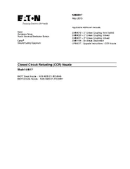
0 INTRODUCTION 20 EQUIPMENT DESCRIPTION 30 DISASSEMBLY 40 INSPECTION 50 SPECIAL TOOLS 60 REASSEMBLY 70 TEST 80 TROUBLES ID: 67865

57347 nozzle seal assembly nozzle 57347 assembly seal housing piston handle parts flow position ccr unit ring part body item remove coupling

Share:

Link:

Embed:

Download Presentation from below link

Download Pdf The PPT/PDF document "Eaton Aerospace Group Fluid Electrical ..." is the property of its rightful owner. Permission is granted to download and print the materials on this web site for personal, non-commercial use only, and to display it on your personal computer provided you do not modify the materials and that you retain all copyright notices contained in the materials. By downloading content from our website, you accept the terms of this agreement.


Presentation Transcript

Eaton Aerospace Group Fluid & Electrical Distribution Division Carter ® Ground Fueling Equipment SM64017 May 20 1 3 Applicable additional manuals: SM64019 – 2” Unisex Coupling, Non - Valved SM64020 – 2” Unisex Coupling, Valved SM64031 – 3” Unisex Cou pling, Valved SM61154 - Dry Break Disconnect UP64017 - Upgrade Instructions - CCR Nozzle Closed Circuit Refueling (CCR) Nozzle Model 64017 64017 Basic Nozzle - NSN 4930 - 01 - 363 - 6449 64017Z Arctic Nozzle - NSN 4930 - 01 - 370 - 3061 SM64017 May 20 1 3 2 TABLE OF CONTEN TS P age 1.0 INTRODUCTION ................................ ................................ ................................ . 3 2.0 EQUIPMENT DESCRIPTION ................................ ................................ ............. 3 3.0 DISASSEMBLY ................................ ................................ ................................ ... 5 4.0 INSPECTION ................................ ................................ ................................ ...... 6 5.0 SPECIAL TOOLS ................................ ................................ ................................ 7 6.0 REASSEMBLY ................................ ................................ ................................ .... 7 7.0 TEST ................................ ................................ ................................ ................... 8 8.0 TROUBLESHOOTING ................................ ................................ ...................... 10 9.0 ILLUS TRATED PARTS CATALOG ................................ ................................ .. 10 FIGURE 1 - OPTIONS VIEW ................................ ................................ .................... 14 FIGURE 2 - PARTS BREAKDOWN ................................ ................................ .......... 15 FIGURE 2A - MAIN BODY SEAL INSTALLATION ................................ ................... 16 FIGURE 3 - ASSEMBLY TOOLS ................................ ................................ .............. 17 FIGURE 4 - USE OF 220284 TOOL ................................ ................................ ......... 18 FIGURE 5 - USE OF 220284 TOOL ................................ ................................ ......... 19 SM64017 May 20 1 3 3 MAINTENANCE, OVERHAUL & TEST INSTRUCTIONS MODEL 64017 CLOSED CIRCUIT REFUELING NOZZLE 1.0 INTRODUCTION This manual furnishe s detailed instructions covering the operation, maintenance and overhaul of Eaton’s Carter ground fueling equipment product line Model 64017 Closed Circuit Refueling (CCR) Nozzle. It is designed in accordance with MIL - N - 52747 F ( AT ), Type I. The Arctic versi on, 64017Z, is designed in accordance with MIL - N - 52747, Type II, Class A and MIL - N - 53094. There are several options available when purchasing a unit as explained in paragraph 2.2 below. The original nozzle was designed to utilize a diaphragm assembly as the main control element. The operation of the unit in the field in the dry condition, although not specifically required in the specification, tends to cause premature failure of the diaphragm causing external leakage. In addition, the specification does not address external leakage at any inlet pressure less than 5 psig although it is quite common for the nozzle to be stored with less inlet pressure caused by “head” pressure only. In this condition, it has been found that leakage from the connecting end o f the nozzle did result. A new pressure energized Teflon seal has been incorporated. The later nozzles, serial number 5804 and subsequent, all are equipped with both the piston assembly and Teflon seals. If the nozzle to be overhauled is serial number 580 3 or lower manual UP64017 will be required to explain the upgrade procedure. UP64017 is provided in any of the upgrade kits listed in paragraph 9.0 or it is available from our web site www.eaton.com o r a n Eaton Carter ground fueling equipment distributor. If the serial number is 5804 or the nozzle has previously been upgraded, only this manual is required. 2.0 EQUIPMENT DESCRIPTION 2.1 DESCRIPTION Model 64017 CCR Nozzle and a closed circu it refueling receiver mounted in a vehicle fuel tank comprise a closed circuit refueling system. It is designed for fueling under pressure with optimum speed, minimum loss of fuel and safety. The refueling system is grounded and bonded and allows the vehi cle to be refueled while engines are in operation without danger. The CCR Nozzle is capable of functioning as an on - off valve, in addition to its pressure regulator capabilities. The CCR Nozzle pressure regulator device performs in conjunction with a close d circuit receiver orifice to comprise a flow control unit. This unit allows fuel to enter the vehicle at a specified flow rate. A bonding cable is provided for discharge of any static electric charge. A strainer assembly is a part of CCR Nozzle inlet. The CCR Nozzle is designed to mate, also, with a G ravity F ill A dapter assembly ( GFA ) , Model 64014 (MIL - N - 52748) for standard service or 64033 (MIL - N - 53093) for a rctic service, for use in refueling vehicles that do not have the appropriate receiver. 2.2 OPTIONS A VAILABLE Model 64017 CCR Nozzle is available with the options listed in the table below. This manual covers all such options. TABLE OF OPTIONS MODEL 64017 CCR NOZZLE The basic model number 64017 may be modified to include the options shown below by addin g the appropriate suffix letter(s) to the model number. The basic part number, 64017, is a CCR m ozzle that meets the requirements of MIL - PRE - 52747F(AT) (previously MIL - N - 52747), Type I, tan in color, including a 100 - mesh screen, 2” female c amlock inlet fit ting and 15 ft. bonding cable. Option Letter Description A Same as standard nozzle except the 2” c amlock inlet fitting is not supplied B Same as standard nozzle except the 2" c amlock inlet fitting is replaced by a non - valved unisex coupling, (640 3 19 22 ). This unit meets the requirements of MIL - N - 52747, Type I, Class B, tan in color. C Standard nozzle with 100 - mesh screen and housing less camlock inlet fitting. Inlet is 2" female NPT. D Same as standard nozzle except inlet screen housing and camlock fitt ing is replaced with a male adapter to interchange with underwing nozzles that mate with Model 61154 Female Half Dry Break QD. Includes 100 - mesh screen. SM64017 May 20 1 3 4 Option Letter Description E Same as "B" option except unisex coupling is valved (64 3 20 22 ). F Basic nozzle except replaces inle t c amlock with 3” 64031 Unisex Coupling with 100 - mesh strainer. G Add to basic, options B or E to conform to green color requirement of specification. Z Arctic service nozzle in accordance with MIL - N - 52747, Type II, Class A and MIL - N - 53094. Includes all the same features of the standard nozzle. Green color only available. 2.3 EQUIPMENT OPERATION 2.3.1 SAFETY INTERLOCKS The control handle is a two - position (flow or open, "up" to no - flow or closed, "down") device which controls the flow of fuel th rough the nozzle. In normal operation, the handle should be in the closed and locked position. There is no lock in the open position. The nozzle control handle can be moved to the open position, once unlatched, however unless the nozzle is attached to the appropriate receiver, the nozzle will not open to allow flow. This interlock provides a safety feature to prevent inadvertent opening unless attached to the receiver. 2.3.2 OPERATION INSTRUCTIONS To commence the actual refueling operation, the CCR must first be attached to a receiver, then the side mounted latch must be depressed and then the flow control handle can be moved to the open position (or up). An emergency disconnect during the fueling operation may be accomplished at any time by simply pullin g the collar away from the receiver. The flow control handle will remain in the up position but the CCR will automatically close. A red colored pin is provided to serve as a visual indication of the nozzle being in the closed or no - flow position. This pin extends or retracts into the housing at the flow control handle end. Operation of the CCR Nozzle should be as follows: • Insert ground plug into vehicle and/or attach alligator clip to unpainted metal on vehicle. Do not attach to propeller or rad io antenna. Nozzle and vehicle are now bonded and grounded. WARNING! Grounding must be accomplished before making contact of nozzle to vehicle. • Remove dust cap from nozzle coupling end by pulling on collar in a motion away from the dust cap. The locking lugs will be positioned to allow the dust cap to be removed. The stayback detents will keep the collar in the pulled back position. It will be in a position to be installed onto the vehicle receiver. • The flow control handle should be in the no - flow or c losed (down) position to make it easier to attach the unit to the receiver. If the handle is in the open (up) position, immediate flow can result when the CCR Nozzle is attached. • Attach the nozzle to the receiver with a straight push - on motion. A positiv e connection is indicated by the collar moving forward with an audible "click". • Open unit by depressing side mounted latch and moving handle to open position (or up). NOTE Completion of filling is controlled by the vehicle control valves. Extension of th e red indicator pin indicates closure of the nozzle regulator valve. The nozzle may cut on and off to top off tanks where vehicles use multiple fuel tanks. • Return handle to the no - flow or closed (down) and latched position. • Disconnect nozzle from rece iver by pulling on collar in a motion away from vehicle. Disconnect vehicle grounding plug and/or clip. Replace dust cap in coupling end of nozzle. 2.3.3 PREVENTATIVE MAINTENANCE CHECKS - EACH REFUELING OPERATION The following checks should be accomplish ed before each refueling operation: • Ascertain that the flow control handle is in the no - flow or closed position (down). • After removing dust cap and before attaching nozzle to receiver, check the coupling end of the nozzle to assure that there are thre e stayback lugs and nine locking lugs visible. If any are missing, the nozzle should not be utilized before it is repaired. • There should be no external leakage from any place on the nozzle or the connection to the hose. • The bonding cables should be p resent and not frayed or damaged in any way. The grounding plug and clip should not be damaged in anyway. SM64017 May 20 1 3 5 3.0 DISASSEMBLY Refer to Figures 1 and 2 for the item numbers listed in the text below. (Items with a prefix of "1 - " are in F igure 1 and those with a prefix of "2 - " are found in Figure 2. 3.1 BONDING CABLE ASSEMBLY (2 - 1) To remove Bonding cable Assembly (2 - 1) first remove Screw (2 - 2). This will separate Plug Cable Assembly (2 - 4) and Clip Cable Assembly (2 - 3) from unit. 3.2 DUST PLUG ASSEMBLY (2 - 5) The cable attachment for the Dust Cap Assembly (2 - 5) is removed when the above Bonding Cable Assembly (2 - 1) is removed. To remove the Dust Cap Assembly (2 - 5) from the nozzle, pull back on the Collar (2 - 32) to release it. Dust Ca p Assembly (2 - 5) is provided only as an assembly and further disassembly is not needed. 3.3 WIPER SEAL (2 - 6) With the flow control handle in the closed position, reach inside the coupling end and remove and discard the Wiper Seal (2 - 6). See note in Ta ble 2 , Section 9.0 under item 2 - 6 for more information on this part. Push the Piston Compression Tool, part number 220283, into the coupling end of the nozzle until it latches. 3.4 COUPLING END OF NOZZLE Before proceeding further be sure that the op ening handle is in the “open” position. With the Piston Compression Tool, 220283, still installed in the nozzle, use the Poppet Tool, 220329, to remove the Poppet (2 - 14). While holding the Piston Compression Tool 220283, pull back on the Collar (2 - 3 2) to release and remove the Piston Compression Tool 220283, Seal Sleeve (2 - 30), Spring (2 - 31) and Flow Guide (2 - 50). Discard Seal Sleeve (2 - 30). Generously apply isopropyl alcohol between Collar (2 - 32) and Housing (2 - 34) to lubricate threads. Use the B ody Wrench, part number 220281, to remove Body (2 - 34) from Housing (2 - 15). Maintain pressure on wrench to prevent force of actuating springs from causing a sudden separation of parts when the threads of the Body (2 - 34) are disengaged from the Housing (2 - 1 5). Also, when turning the Body Wrench 220281, lightly pull back on the Collar (2 - 32) such that the Body (2 - 34) can rotate easily relative to the Collar (2 - 32). The Collar (2 - 32) can then be removed along with the remainder of the bits and pieces, inclu ding three Stayback Detents (2 - 33), nine Locking Lugs (2 - 36), Lug Wire (2 - 35), Lug Retaining Ring (2 - 37), Stay Back Spring (2 - 38), Spring Retainer Ring (2 - 39) and Spring (2 - 40). Care should be exercised so as not to lose the Stayback Detents (2 - 33) and L ocking Lugs (2 - 36). Remove and discard Packing (2 - 41) from Housing (2 - 15). Remove and discard Seal (2 - 6B) and Backup (2 - 6A) from Body (2 - 34). 3.5 FLOW CONTROL LATCH END OF NOZZLE Compress the Valve Actuator Latch (2 - 24) and place the flow control handl e in the open (up) position. Remove four Screws (2 - 7) from End Cover (2 - 9). Do not remove Screw (2 - 7) from Cover (2 - 9) unless either the Locking Pin (2 - 10) or the Screw (2 - 7) are to be replaced. If these parts are to be disassembled, use a soft jaw chuck o r vice to hold the Locking Pin (2 - 10) while removing the Screw (2 - 7). Regulator Spring Retainer (2 - 11) and Regulator Spring (2 - 12) can then be removed. Pull Piston (2 - 13) with its attached parts from the unit. Remove the four Screws (2 - 26A) retaining the B ushing (2 - 26). This ring can be reused by reversing it and reinstalling it onto the Piston (2 - 13). Once it has been used on both sides, discard Bushing (2 - 26). Unscrew Nut (2 - 13B) to remove Seal (2 - 13A). Discard Seal (2 - 13A). Unscrew Position Indicator (2 - 29) from Piston (2 - 13) if it is to be replaced. Remove four handle Screws (2 - 7) and Valve Actuator Handle (2 - 17). Remove six Screws (2 - 27) and Sleeve (2 - 28). Remove and discard O - ring (2 - 28A). Remove Screw (2 - 18) from one side of the unit. This all ows the removal of Side Plate (2 - 21), two Washers (2 - 19) and Bushing (2 - 20). Screw (2 - 22) and Actuating Cam (2 - 23) should not be removed from Side Plate (2 - 21) unless one is damaged and replacement is needed. If replacement is needed, use a soft jaw chuck or vice to hold Actuating Cam (2 - 23) while removing Screw (2 - 22). Note : When removing Side Plate (2 - 21) from the side of the unit where the Valve Actuator Latch (2 - 24) is located, compress the Valve Actuator Latch (2 - 24) for the removal. Then the Valve Actuator Latch (2 - 24) and Detent Spring (2 - 25) can be removed from the Housing (2 - 15). 3.6 INLET STRAINER HOUSING - 64017, 64017B, C & E only Unscrew Strainer Body (2 - 45) from unit to inspect or remove Strainer (2 - 44). There is no need to disassemble St rainer Housing (2 - 42) from Housing (2 - 15) unless repair or replacement is needed. Packing (2 - 43) and Strainer (2 - 44) can then be removed. Discard Packing (2 - 43). It is not necessary to disassemble Coupling Half (2 - 48) or Unisex Couplings (1 - 4) or (1 - 10) fr om Strainer Body (2 - 45) unless repair or replacement is SM64017 May 20 1 3 6 needed. Gasket (2 - 47) can be replaced by removing Plug (2 - 49). Discard Gasket (2 - 47). 3.7 NON - VALVED UNISEX INLET - 64017B Only (1 - 4) Refer to Service Manual SM64019 (64319) for maintenance inst ructions for this part of the unit. 3.8 UNDERWING INTERCHANGE MALE ADAPTER INLET - 64017D Only (1 - 5) Refer to Service Manual SM61154 for maintenance instructions for this part of the unit. Strainer (1 - 7) can be removed for inspection and/or replacement by removing Retainer (1 - 8). Do not remove Adapter (1 - 6) from unit unless repair or replacement is needed. 3.9 VALVED UNISEX INLET - 64017E Only (1 - 10) Refer to Service Manual SM64020 (64320) for maintenance instructions for this part of the unit. 3.10 V ALVE D UNISEX INLET – 64017F Only (1 - 10A) Refer to Service Manual SM64031 for maintenance instructions for this part of the unit. 4.0 INSPECTION 4.1 PARTS REPLACEMENT Replace the following items with new parts, available in the vari ous kits listed in Section 9.0, during maintenance: Item no. Part no. Name Quantity Used on 2 - 6*** 201201 - 134 Seal 1 All 2 - 6A 220778 Backup 1 All 2 - 6B 220779 Seal 1 All 2 - 13A 221567 Seal 1 All 2 - 20 220101 Bushing 2 All 2 - 28A MS29513 - 125 O - ring 1 A ll 2 - 30 220083 - 1 Seal 1 All but Z 2 - 30 220083 - 2 Seal 1 Z 2 - 41 MS29513 - 136 Packing 1 All 2 - 43 MS29513 - 226 Packing 1 All 2 - 47 MS27030 - 6 Gasket 1 All but Z 2 - 47 220126 - 6 Gasket, Arctic 1 Z * 200146 Seal, Unisex 2 B, E * MS29513 - 010 O - ring 1 B, E * MS29513 - 136 O - ring 1 B, E * MS29513 - 226 O - ring 1 B, E * MS29513 - 228 O - ring 1 B, E * 220157 Seal, Upstream 1 E * 47363 Seal Assembly, Downstream 1 E * MS29513 - 014 O - ring 1 E * MS29513 - 133 O - ring 1 E * MS29513 - 134 O - ring 1 E * MS29513 - 009 O - ring 1 F * 220465 Seal 1 F * 220467 Seal 1 F * MS29513 - 234 O - ring 1 F * MS29512 - 03 O - ring 1 F * MS29513 - 016 O - ring 1 F * MS29513 - 016 O - ring 1 F ** 221266 Seal 1 D * Items from SM64019, SM64020 or SM64031 that are not shown in this manual. ** Item from SM61 154 that is not shown in this manual. *** See note in Table 2 , item 2 - 6 for more information on this item. SM64017 May 20 1 3 7 4.2 GENERAL INSPECTION Inspect all metal parts for dings, gouges, abrasions, etc. Use 300 grit paper to smooth and remove sharp edges. Replace any part with damage exceeding 16% of local wall thickness. Use alodine 1200 to touch up bared aluminum. 4.3 DETAIL INSPECTION 4.3.1 BONDING CABLE ASSEMBLIES Inspect Cables (2 - 3 & 2 - 4) for signs of unraveling, wear or other damage. Inspect plug and cl ip for possible damage. Replace any worn parts as required. 4.3.2 DUST CAP ASSEMBLY (2 - 5) Inspect Dust Cap Assembly (2 - 5) for cracks or other damage, check wire for fraying or other damage. Replace as required. 4.3.3 STAYBACK DETENTS (2 - 33) & LOCKING LU GS (2 - 36) Inspect the Stayback Detents (2 - 33) and Locking Lugs (2 - 36) for cracks or broken pieces. 4.3.4 BUSHING (2 - 26) Inspect Bushing (2 - 26) for wear or damage to both sides of the part. Replace or install in the reversed direction from any apparent wear as needed. 4.3.5 SLEEVE (2 - 28) Inspect inside diameter for scratches that may cause leakage. Do not attempt to polish this part. Replace if scratched. 5.0 SPECIAL TOOLS The following special tools are recommended for proper repair and or overhaul of the nozzle: • 220281 Body Wrench • 220283 Piston Compression Tool • 220284 Locking Lug Assembly Tool • 220329 Poppet Tool The above tools are available on special order from a Carter distributor or directly from the factory. All f our tools can be ordered as a single kit under part number KD64017 - 12. 6.0 REASSEMBLY Reassemble the nozzle in the reverse order of disassembly taking note of the following items: 6.1 INLET FITTINGS Refer to the appropriate Se rvice Manuals, listed on the front cover for information regarding the assembly of the various inlets, if the unit is other than the basic 64017 or option C. If the Strainer Housing (2 - 42), Coupling Half (2 - 48), Underwing Nozzle Interchange Adapter (1 - 5) , Unisex Couplings (1 - 4) or (1 - 10) were removed for replacement or repair they must be reinstalled with a thread seal. If Teflon tape is utilized, no more than one and on - half wraps of tape should be used otherwise damage to the mating parts may occur. Any fuel resistant paste seal is acceptable. Although available as a separate spare part, Gasket (2 - 47) is also furnished as a part of the Coupling Half Assembly (2 - 48). 6.2 FLOW CONTROL LATCH END OF NOZZLE Place O - ring (2 - 28A) into the groove in Sleeve (2 - 28) and assemble into Housing (2 - 15) using Screws (2 - 27). Torque the Screws (2 - 27) to 23 in - lbs. Screw Position Indicator (2 - 29) into the Piston (2 - 13). Place Seal (2 - 13A) onto threaded end of Piston (2 - 13) with the open end (spring shows through it) facing toward the treaded end. Screw Nut (2 - 13B) onto Piston (2 - 13) and torque in place to 125 in - lbs. Slip Bushing (2 - 26) over small end of Piston (2 - 13) and attach to the flanged end with four Screws (2 - 16A). Tighten screws sufficiently to seat the Ri ng (2 - 26) only, do not over tighten. Using a soft jaw chuck or vise, assemble the Actuating Cam (2 - 23) on one of the Handle Side Plates (2 - 21). Affix in place with Screw (2 - 22) and torque to 100 + 10 in - lb. Repeat with the other set of similar parts. Star t with the side of the Housing (2 - 15) that does not include the Valve Actuator Latch (2 - 24). Position Actuating Cam (2 - 23) into banana shaped slot in Housing (2 - 15) such that the Actuating Cam (2 - 23) is positioned between the Bushing (2 - 26) and the Sleeve (2 - 28). It will be necessary to attempt assembly with the Handle Side Plate (2 - 21) positioned in nozzle open position to achieve proper assembly. Place a Washer (2 - 19) between the Handle Side Plate (2 - 21) and the Housing (2 - 15). Insert Bushing (2 - 20) into the Handle Side Plate (2 - 21). Place a Washer (2 - 19) on the outside of the Handle Side Plate (2 - 21) and affix parts to unit using Screw (2 - 18). Torque to 125 ± 10 in. - lb. Insert Spring (2 - 25) into cavity of Housing (2 - 15) followed by the Valve Latch Actua tor (2 - 24). Holding this in the approximate position, repeat the assembly of the Handle Side Plate (2 - 21), Washer (2 - 19), Bushing (2 - 20), second SM64017 May 20 1 3 8 Washer (2 - 19) and Screw (2 - 18). Torque to 125 ± 10 in. - lb. Place Valve Actuator Handle (2 - 17) between the two Handle Side Plates (2 - 21) and secure with four Screws (2 - 7). Torque to 35 ± 5 in. - lb. If the Lock Pin (2 - 10) was disassembled from the End Cover (2 - 9) use a soft jaw chuck or vise to reinstall using Screw (2 - 7). The Lock Pin (2 - 10) will be assembled int o one of the two holes provided in Piston (2 - 13). It will be necessary to rotate in Piston (2 - 13) to position one of the holes into the proper position. Place End Cover (2 - 9) temporarily in place to check the location of the hole in the in Piston (2 - 13) w ith respect to the Lock Pin (2 - 10). Install the Spring (2 - 12) and position the Reducer Spring Retainer (2 - 11) over the Position Indicator (2 - 29). Install the End Cover (2 - 9) and Lock Pin (2 - 10) assembly such that the hole in the in Piston (2 - 13) accepts t he Lock Pin (2 - 10). Tighten in place using the four Screws (2 - 7), torquing sufficiently to retain in place. Rotate handle to closed position to check that everything was assembled correctly. Leave the handle in this position for the next assembly operatio n. Note: Moving the handle to the open position while performing the next operation may result in damage to the Lock Pin (2 - 10). Insert Flow Guide (2 - 50), Spring (2 - 31) and Sleeve Seal (2 - 30) into the opposite end of the Housing (2 - 15). Insert the Piston Compression Tool, 220283, into the unit to hold the Sleeve Seal (2 - 30) away from the Poppet (2 - 14) when it is installed. With the Piston (2 - 13) held in place by the Lock Pin (2 - 10); thread Poppet (2 - 14) into the opposite end of the Housing (2 - 15) and tig hten securely in place using Poppet Tool 220329. NOTE: Do not remove the Piston Compression Tool, 220283, until the nozzle is fully reassembled. At this point, the Piston Compression Tool, 220283, can be removed from the nozzle by pulling back on the Col lar (2 - 32). 6.3 COUPLING END OF NOZZLE Install Backup (2 - 6A) into the inside groove closest to the threaded end of the Body (2 - 34). The Backup (2 - 6A) is split to facilitate installation. Note that the thin lip part of the Backup (2 - 6A) faces the threade d portion of the Body (2 - 34). Then install the Seal (2 - 6B) into the groove left adjacent to the Backup (2 - 6A). The open end containing the spring must face the threaded end of the Body (2 - 34). See Figure 2A for installation details. Smooth the Seal (2 - 6B) with a finger to assure that it is fully installed and to remove any wrinkles. Install Packing (2 - 41) into groove in Housing (2 - 15) making sure that it is smoothly installed. Referring to Figure 4, install Lug Wire (2 - 35) onto the groove in the nose of t he Body (2 - 34). Insert this assembly into the Lug Assembly Tool, 220284. The Lug Assembly Tool should be placed into a vice during this operation. Insert the three Stayback Detents (2 - 33) into the spaces in the Body (2 - 34) being sure to space the Stayback Detents (2 - 33) into every fourth space. Referring to Figure 5, insert the nine Locking Lugs (2 - 36) with three Locking Lugs (2 - 36) between each pair of Stayback Detents (2 - 33). Slide Lug Retainer Ring (2 - 37) and Spring (2 - 38) onto the Body (2 - 34) being sur e that the chamfered end of Lug Retainer Ring (2 - 37) is placed downward toward the Locking Lugs (2 - 36). Slide the Collar (2 - 32) over the assembly and work it down over the Locking Lugs (2 - 36) and Stayback Detents (2 - 33). Install Spring Retainer Ring (2 - 3 9) and Spring (2 - 40) into the above assembly. Slide the Housing (2 - 15) onto the above assembly. Push down on the Housing and rotate the Housing clockwise about one turn to start the threads between the Body (2 - 34) and Housing (2 - 15) and make sure that t he notch in the Collar (2 - 32) lines up with the protrusion on the Housing (2 - 15) after the one turn. Remove nozzle assembly from the Lug Assembly Tool, 220284, and place Housing (2 - 15) in a vise so that the nozzle assembly is facing upward. Using Body Wren ch, 220281, tighten the assembly to 250 in. - lb. t orque to seat the unit snugly. When turning the Body Wrench 220281, lightly pull back on the Collar (2 - 32) such that the Body (2 - 34) can rotate easily relative to the Collar (2 - 32). On all nozzles with seri al numbers 7757 or lower go to 6.3.1, On nozzles with higher serial numbers or where a Body (2 - 34) has a narrow groove go to 6.3.2. 6.3.1 Install Seal (2 - 6) with a Backup Ring (6 - A) in the wider groove. The order of installation is optional. 6.3.2 Install Seal (2 - 6) i n the narrow groove. 6.4 BONDING CABLE ASSEMBLY (2 - 1) & DUST CAP ASSEMBLY (2 - 5) Attach the Bonding cable Assembly (2 - 1) and Dust Cap (2 - 5) to the Housing (2 - 15) using Screw (2 - 2). It is recommended that the Bonding cable (2 - 1) be placed next to the Housing (2 - 15) to gain better electrical conductivity. 7.0 TEST The following test procedures will be accomplished after overhaul: 7.1 TEST CONDITIONS SM64017 May 20 1 3 9 Test media shall be JP - 4, Jet A or odorless kerosene, commercial solvent 140. 7.2 FUNCTIONAL TE ST • Install nozzle in test rig, 70007, in accordance with Figure A. Open nozzle and Valve 8 to recirculate the test fluid through the system to bleed all trapped air. •  Increase inlet pressure to 25 psig and close Valve 8. The visual flow Indicator (2 - 29) should be visible indicating that the unit had also closed. Close the nozzle with the flow control handle. • Open Valve 8 and increase the inlet pressure to 125 psig. Slowly open the flow control handle. Adjust the flow rate by restricting Valve 8 t o maintain the inlet pressure at 125 psig. Close Valve 8 and check to see that the nozzle has closed (visual Indicator (2 - 29) visible). Close the nozzle and disconnect from the system. 7.3 CONTINUITY TEST With nozzle removed from the test rig install Coup ling Half Plug (2 - 49). Check continuity across the following locations on the nozzle. The resistance shall not exceed 10 ohms. • Locking Lugs (2 - 36) and Grounding Clip (2 - 3). • Locking Lugs (2 - 36) and Grounding Plug (2 - 4). 7.4 PROOF PRESSURE • With the n ozzle closed and not connected to the test system, apply 5 psig inlet pressure for one minute minimum. There shall be no leakage. • Slowly increase the inlet pressure to 180 psig for one minute minimum. There shall be no leakage or other damage to the no zzle. • Connect the nozzle to the test system and open the nozzle with Valve 8 closed. Repeat the above two tests. 1. Nozzle assembly 2. Test adapter, outlet (note 1) 3. Test adapter, inlet (note 1) 4. Pressure gauge, 0 - 300 psig 5. Hydraulic pump, 0 - 300 psig 6. Filter, 15 micron 7. Fluid reservoir, 10 - 20 gallon 8. 3/4” ball valve NOTES: 1. 3/4” NPT tapped hole in both adapters for hose connections . 2. ITEMS 2 - 7 may be procured as 70007 test system . FIGURE A TEST SETUP SM64017 May 20 1 3 10 8.0 TROUBLESHOOTING 8.1 Leakage From Coupling End During Refueling Remove nozzle from the vehicle receiver and move the flow control handle to the open condition to position nose seal on Sleeve Seal (2 - 30) closer to the outlet. Inspect seal for damage or foreign matter. If seal is damaged r eturn the nozzle to the shop for replacement. If foreign matter present wipe the seal clean. Leakage could also be coming from a damaged or worn Seal (2 - 6B) (Teflon) or from a damaged Packing (2 - 41). Return nozzle to the shop for overhaul. 8.2 Leakage From Flow Control End Piston Seal (2 - 13A) could be damaged or Sleeve (2 - 28) could be scratched. Return nozzle to the shop for overhaul. 8.3 Leakage From Coupling End with Nozzle in Closed Position Sleeve Seal (2 - 30) can be damaged or worn under Poppet (2 - 14). Return nozzle to the shop for overhaul. Seal (2 - 6A) could be damaged or worn. Check for damaged Packing (2 - 41). Return nozzle to the shop for overhaul. 8.4 Leakage Between Strainer Housing (2 - 42) and Strainer Body (2 - 45) Damaged or worn Packing ( 2 - 43). Return nozzle to the shop for overhaul. 8.5 Leakage Between Coupling Half and Hose Connection Damaged or worn Gasket (2 - 47). Replace Gasket (2 - 47). 8.6 Handle Fails to Operate Smoothly or Does not Open Unit. Actuating Cam(s) (2 - 23) not assembled between Bushing (2 - 26) and Sleeve (2 - 28). Return nozzle to the shop for overhaul. 8.7 Inadequate Flow from Unit Remove Strainer (2 - 44) and check for presence of foreign material. Clean and return to unit. Seal (2 - 13A) may be damaged and leaking. Extern al leakage from the Flow Control Handle End of the unit should also be present. Return nozzle to the shop for overhaul. 9.0 ILLUSTRATED PARTS CATALOG Table 1.0 tabulates the parts and sub - assemblies comprising the 64 017 CCR Nozzle. The item numbers of the table are keyed to the exploded view of the nozzle diagrammed in Figures 1 and 2. TABLE 1.0 Ref. Figure 1 Fig Item Part Number Description Units / Assy Used on Option Spares/10 units/Yr 1 1 64017 CCR Nozzle, Basic, Type I, Class A, Tan, with strainer housing assy, 2” camlock inlet, dust cap and grounding cable. Various options shown below: 1 Standard - 64017A CCR Nozzle, Basic, Type I, Class A, Tan, with Grounding Cable and 1 - 1/2” Female NPT (no strainer housing assy, camlock or dust cover) 1 A - 64017AG CCR Nozzle, Basic, Type I, Class A, Green, with Grounding Cable and 1 - 1/2” Female NPT (no strainer housing assy, camlock or dust cover) 1 AG - 64017B CCR Nozzle, Basic, Type I, Class A , Tan, with strainer housing assy and 2” non - valved unisex coupler 1 B - 64017BG CCR Nozzle, Basic, Type I, Class A , Green, with strainer housing assy and 2” non - valved unisex coupler 1 BG - 64017C CCR Nozzle, Basic, Type I, Class A, Tan with Grounding Cable and 1 - 1/2” Female NPT, strainer housing assy, camlock and dust cover 1 C - 64017CG CCR Nozzle, Basic, Type I, Class A, Green with Grounding Cable and 1 - 1/2” Female NPT, Strainer Housing Assy, Camlock and Dust Cover 1 CG - 1 64017D CCR Nozzle, Tan with Underwing Interchange 1 - 1/2” Dry Break Adapter 1 D - SM64017 May 20 1 3 11 Fig Item Part Number Description Units / Assy Used on Option Spares/10 units/Yr 1 64017DG CCR Nozzle, Green with Underwing Interchange 1 - 1/2” Dry Break Adapter 1 DG - 64017E CCR Nozzle, Tan with Valved Unisex Coupling 1 E - 64017EG CCR Nozzle, Green with Valved Unisex Coupling 1 EG - 64017G CCR Nozzle, Basic, Type I, Class A, Green, with Strainer Housing Assy, 2” Camlock and Dust Cover 1 G - 64017Z CCR Nozzle, for Arctic Service, Green Z - 2 No part number Strainer Housing Sub - assembly, Tan 1 All but A, G,Z - 3 GF27026 - 11 - T N 2” Camlock Fitting - Tan 1 All but A, G, Z - 3A GF27029 - 11 - TN 2” Cap for item 3 (not shown separately) 1 All but A, G, Z - 4 6431922 Unisex Non - valved Coupling, Tan 1 B - 6431922V Unisex Non - valved Coupling, Green 1 BG - 5 No part number Interch ange Adapter Assy 1 D - 6 44698 Interchange Adapter 1 D - 7 44373 - 100 Screen Assembly 1 D - 8 28092 - 100 Screen, 100 - mesh 1 D - 9 208091 Retainer 1 D - 10 6432022 2” Unisex Valved Coupling, Tan 1 E - 6432022V 2” Unisex Valved Coupling, Gree n 1 EG - 10A 64031CN 3” Unisex Valved Coupling, Tan 1 F - 64031CNV 3” Unisex Valved Coupling, Green 1 FG - TABLE 2.0 Ref. Figure 2 Fig Item Part Number Description Units / Assy Used on Option Spares/10 units/Yr 2 1 47028 Bonding cable Assembly 1 All - 2 GF16998 - 42 Screw 1 All - 3 47029 Clip Cable Assembly 1 All - 4 47030 Plug Cable Assembly 1 All - 5 47025 - 1 Dust Cap Assembly, Tan 1 All but G, Z - 47025 - 2 Dust Cap Assembly, Green 1 G, Z - 6 201201 - 134 Seal ( o n nozzles serial numbe r 7757 and lower use additional item 6A in the wide groove. On serial number 7758 and subsequent where the Body item 34 has a narrow groove use only item 6). (If the Body (34) is replaced with the narrow groove use only Seal (6) regardless of serial number ). 1 All but Z 10 6 M25988/1 - 134 O - Ring 1 Z 10 6A 220778 Ring, Backup (see note under 6 above). 1 All 10 6B 220779 Seal, Teflon 1 All 10 7 LP51958 - 64 Screw 9 All - 8 Left intentionally blank 9 220086 - 1 End Cover, Tan 1 All but G, Z - 22008 6 - 2 End Cover, Green 1 G,Z - 10 220111 Lock Pin 1 All - 11 220097 Reducer Spring Retainer 1 All - 12 220113 Spring 1 All - SM64017 May 20 1 3 12 Fig Item Part Number Description Units / Assy Used on Option Spares/10 units/Yr 2 13 220768 Piston 1 All - 13A 221567 Seal 1 All 10 13B 220777 Nut 1 All - 14 220088 Poppet 1 All - 15 220078 - 1 Housin g, Tan 1 All but G, Z - 15 220078 - 2 Housing, Green 1 G,Z - 16 Left intentionally blank 17 220095 - 1 Handle, Tan 1 All but G, Z - 220095 - 2 Handle, Green 1 G, Z - 18 LP51957 - 108 Screw 2 All - 19 5710 - 179 - 60 Washer 4 All - 20 220101 Bushing 2 Al l 20 21 220090 - 1 Side Plate Handle, Tan 2 All but G, Z - 220090 - 2 Side Plate Handle, Green 2 G,Z - 22 GF16998 - 42L Screw 2 All - 23 220109 Actuating Cam 2 All - 24 220202 Valve Latch Actuator 1 All - 25 C0180 - 026 - 1000S Spring 1 All - 26 22076 9 Bushing 1 All 5 26A GF16997 - 20L Screw 4 All - 27 GF16997 - 21L Screw 6 All - 28 220767 Sleeve 1 All 5 28A MS29513 - 125 O - ring 1 All 10 29 220160 Position Indicator 1 All - 30 220083 - 1 Sleeve Seal 1 All but Z 10 220083 - 2 Sleeve Seal, Arctic 1 Z 10 31 220112 Spring 1 All - 32 220081 - 1 Collar, Tan 1 All but G, Z - 220081 - 2 Collar, Green 1 G, Z 1 33 220104 Stayback Detent 3 All - 34 220080 Body 1 All - 35 220100 Lug Wire 1 All - 36 220093 Locking Lug 9 All - 37 220099 Lug Retainer Ring 1 All - 38 220103 Spring 1 All - 39 220096 Spring Retainer Ring 1 All - 40 220114 Spring 1 All - 41 MS29513 - 136 Packing 1 All 10 42 220120 - 1 Strainer Housing, Tan 1 All but G, Z - 220120 - 2 Strainer Housing, Green 1 G, Z - 43 MS29513 - 22 6 Packing 1 All 10 44 220122 - 100 Strainer 1 All - 45 220121 - 1 Strainer Body, Tan 1 All but G, Z - 220121 - 2 Strainer Body, Green 1 G, Z - 46 GF27026 - 11 - TN Coupling Half, Female, Tan 1 All but G - GF27026 - 11 - GN Coupling Half, Female, Green 1 G - 47 MS27030 - 6 Gasket 1 All 10 220126 - 6 Gasket, Arctic 1 Z 10 48 Left intentionally blank 49 GF27029 - 11 - TN Dust Plug, Tan 1 All but G, Z - GF27029 - 11 - GN Dust Plug, Green 1 G,Z - 50 220326 Flow Guide 1 All - - KD64017 - 1 Special Tool Kit – contains all five special assembly/disassembly tools needed as shown in Figure 3 of SM64017 to overhaul a basic unit with a diaphragm assembly. (Note: Use - 12 for nozzles with piston assembly). - KD64017 - 2 Kit of parts to upgrade Piston to piston assembl y and changes main sleeve seal to Teflon in basic 64017 Nozzle – contains items 6, 6A (2 included – see notes under item 6 above), 6B, 11, 13, 13A, 13B, 20, 26, 26A, 28, 28A, 30, 41, 43 & 47 (normal temperature items only). - KD64017 - 3 Kit of parts to upgrade diaphragm type control to piston type control assembly and changes main SM64017 May 20 1 3 13 Fig Item Part Number Description Units / Assy Used on Option Spares/10 units/Yr sleeve seal to Teflon in 64017Z Nozzle – contains items 6, 6A (2 included – see notes under item 6 above), 6B, 11, 13, 13A, 13B, 20, 26, 26A, 28, 28A, 30, 41, 43 & 47 (low temp erature items only). - KD64017 - 4 Kit of parts to upgrade Piston to piston assembly and changes main sleeve seal to Teflon in 64017B Nozzle – contains appropriate items 6, 6A (2 included – see notes under item 6 above), 6B, 11, 13, 13A, 13B, 20, 26, 26A, 28, 28A, 30, 41, & 43 plus soft goods to replace the parts in the unisex coupling, 64019J. - KD64017 - 5 Kit of parts to upgrade Diaphragm Assembly to piston assembly and changes main sleeve seal to Teflon in 64017D Nozzle - contains items 6, 6A (2 includ ed – see notes under item 6 above), 6B, 11, 13, 13A, 13B, 20, 26, 26A, 28, 28A, 30, 41 & 43 plus 220709 - 232 Seal for the D option. - KD64017 - 6 Kit of parts to upgrade diaphragm to piston assembly and changes main sleeve seal to Teflon in 64017E Nozzle - contains items 6, 6A (2 included – see notes under item 6 above), 6B, 11, 13, 13A, 13B, 20, 26, 26A, 28, 28A, 30, 41& 43 plus soft goods to replace the parts in the unisex coupling, 64020J. - KD64017 - 7 Kit of parts to replace the soft goods in the basic 64017 Nozzle that has already been upgraded - contains items 6, 6A (2 included – see notes under item 6 above), 6B, 13A, 20, 28A, 30, 41, 43 & 47 (normal temperature items only). - KD64017 - 8 Kit of parts to replace the soft goods in the basic 64017Z Noz zle that has already been upgraded - contains items 6, 6A (2 included – see notes under item 6 above), 6B, 13A, 20, 28A, 30, 41, 43 & 47 (low temperature items only). - KD64017 - 9 Kit of parts to replace the soft goods in the basic 64017 Nozzle that has a lready been upgraded - contains items 6, 6A (2 included – see notes under item 6 above), 6B, 13A, 20, 28A, 30, 41& 43 plus soft goods to replace the parts in the unisex coupling, 64019J. - KD64017 - 10 Kit of parts to replace the soft goods in the basic 64 017 Nozzle that has already been upgraded - contains items 6, 6A (2 included – see notes under item 6 above), 6B, 13A, 20, 28A, 30, 41 & 43 plus 220709 - 232 Seal. - KD64017 - 11 Kit of parts to replace the soft goods in the basic 64017 Nozzle that has alre ady been upgraded - contains items 6, 6A (2 included – see notes under item 6 above), 6B, 13A, 20, 28A, 30, 41 & 43 plus soft goods to replace the parts in the unisex coupling, 64020J. - KD64017 - 12 Kit of 4 special tools to repair any 64017 Nozzle with t he latest configuration piston assembly. (See Figure 3 less the diaphragm tool). - KD64017 - 13 Kit of parts for standard nozzles to replace obsolete 220094 - 1 Seal with items 6 & 6A. - KD64017 - 14 Kit of parts for arctic nozzles 64017Z to replace obsolete 220094 - 1 Seal with items 6 & 6A. - KD64017 - 15 Kit to upgrade nozzles for use in extremely dusty environment. Includes 47484 & 47485. SM64017 May 20 1 3 14 Notes: 1. All part numbers beginning with "GF" are interchangeable with those beginning with either "AN" or "MS". If the "GF" is followed by three numbers, it is interchangeable with and "AN" part, otherwise it is interchangeable with an "MS" part of the same number. 2. Spare parts recommended are for a set of ten nozzles being overhauled at a frequency of once each yea r. The actual frequency of overhaul may be longer or shorted depending upon the number of refueling cycles used. This is intended as a guide only. 3. See SM64031 for kits required along with KD64017 - 7 to overhaul a 64017F, 4. The 47484 Piston Assembly incl udes items 13A, 13B; 26A & 29. Also includes replacement parts for items for items 13 (221501 Piston) & 26 (221502 Bushing) for nozzles modified to work in heavy dust conditions. 5. The 47485 Seal Sleeve Assembly includes replaces item 27 and includes re placements for item 28 (221500) & 28A (MS29513 - 028). 6. There currently is no option to offer this modification in a new nozzle. One can only modify an existing nozzle to obtain this option. If new nozzles of this type are desired, contact Carter for a c hange in the options. FIGURE 1 - OPTIONS VIEW SM64017 May 20 1 3 15 FIGURE 2 - PARTS BREAKDOWN SM64017 May 20 1 3 16 FIGURE 2A - MAIN BODY SEAL INSTALL ATION SM64017 May 20 1 3 17 FIGURE 3 - ASSEMBLY TOOLS SM64017 May 20 1 3 18 FIGURE 4 - USE OF 220284 TOOL TO INSTALL STAY BACK DETENTS (33) SM64017 May 20 1 3 19 FIGURE 5 - USE OF 22 0284 TOOL TO INSTALL LOCKING LUGS (36) Eaton Aerospace Group Fluid & Electrical Distribution Division 9650 Jeronimo Road Irvine, CA USA 92618 Ph: (949) 452 - 9500 Fax: (949) 452 - 9992 Eaton Aerospace Group Fluid & Electrical Distribution Division 9650 Jeronimo Road Irvine, CA USA 92618 Ph: (949) 452 - 9500 Fax: (949) 452 - 9992 �� SM64017 May 13 Fig Item Part Number Description Units / Assy Used on Option Spares/10 units/Yr 1 64017DG CCR Nozzle, Green with Underwing Interchange 1 - 1/2” Dry Break Adapter 1 DG - 64017E CCR Nozzle, Tan with Valved Unisex Coupling 1 E - 64017EG CCR Nozzle, Green with Valved Unisex Coupling 1 EG - 64017G CCR Nozzle, Basic, Type I, Class A, Green, with Strainer Housing Assy, 2” Camlock and Dust Cover 1 G - 64017Z CCR Nozzle, for Arctic Service, Green Z - 2 No part number Strainer Housing Sub - assembly, Tan 1 All but A, G,Z - 3 GF27026 - 11 - T N 2” Camlock Fitting - Tan 1 All but A, G, Z - 3A GF27029 - 11 - TN 2” Cap for item 3 (not shown separately) 1 All but A, G, Z - 4 6431922 Unisex Non - valved Coupling, Tan 1 B - 6431922V Unisex Non - valved Coupling, Green 1 BG - 5 No part number Interch ange Adapter Assy 1 D - 6 44698 Interchange Adapter 1 D - 7 44373 - 100 Screen Assembly 1 D - 8 28092 - 100 Screen, 100 - mesh 1 D - 9 208091 Retainer 1 D - 10 6432022 2” Unisex Valved Coupling, Tan 1 E - 6432022V 2” Unisex Valved Coupling, Gree n 1 EG - 10A 64031CN 3” Unisex Valved Coupling, Tan 1 F - 64031CNV 3” Unisex Valved Coupling, Green 1 FG - TABLE 2.0 Ref. Figure 2 Fig Item Part Number Description Units / Assy Used on Option Spares/10 units/Yr 2 1 47028 Bonding cable Assembly 1 All - 2 GF16998 - 42 Screw 1 All - 3 47029 Clip Cable Assembly 1 All - 4 47030 Plug Cable Assembly 1 All - 5 47025 - 1 Dust Cap Assembly, Tan 1 All but G, Z - 47025 - 2 Dust Cap Assembly, Green 1 G, Z - 6 201201 - 134 Seal ( o n nozzles serial numbe r 7757 and lower use additional item 6A in the wide groove. On serial number 7758 and subsequent where the Body item 34 has a narrow groove use only item 6). (If the Body (34) is replaced with the narrow groove use only Seal (6) regardless of serial number ). 1 All but Z 10 6 M25988/1 - 134 O - Ring 1 Z 10 6A 220778 Ring, Backup (see note under 6 above). 1 All 10 6B 220779 Seal, Teflon 1 All 10 7 LP51958 - 64 Screw 9 All - 8 Left intentionally blank 9 220086 - 1 End Cover, Tan 1 All but G, Z - 22008 6 - 2 End Cover, Green 1 G,Z - 10 220111 Lock Pin 1 All - 11 220097 Reducer Spring Retainer 1 All - 12 220113 Spring 1 All - 1 �� SM64017 May 13 8.0 TROUBLESHOOTING 8.1 Leakage From Coupling End During Refueling Remove nozzle from the vehicle receiver and move the flow control handle to the open condition to position nose seal on Sleeve Seal -30) closer to the outlet. Inspect seal for damage or foreign matter. If seal is damaged return the nozzle to the shop for replacement. If foreign matter present wipe the seal clean. Leakage could also be coming from a damaged or worn Seal (2-6B) (Teflon) or from a damaged Packing (2-41). Return nozzle to the shop for overhaul.8.2 Leakage From Flow Control End Piston Seal (2-13A) could be damaged or Sleeve (2-28) could be scratched. Return nozzle to the shop for overhaul.8.3 Leakage From Coupling End with Nozzle in Closed Position Sleeve Seal (2-30) can be damaged or worn under Poppet (2-14). Return nozzle to the shop for overhaul. Seal (2-6A) could be damaged or worn. Check for damaged Packing (2-41). Return nozzle to the shop for overhaul.8.4 Leakage Between Strainer Housing (2-42) and Strainer Body (2-45) Damaged or worn Packing (2-43). Return nozzle to the shop for overhaul. 8.5 Leakage Between Coupling Half and Hose Connection Damaged or worn Gasket (2-47). Replace Gasket (2-47). 8.6 Handle Fails to Operate Smoothly or Does not Open Unit. Actuating Cam(s) (2-23) not assembled between Bushing (2-26) and Sleeve (2-28). Return nozzle to the shop for overhaul. 8.7 Inadequate Flow from Unit Remove Strainer (2-44) and check for presence of foreign material. Clean and return to unit. Seal (2-13A) may be damaged and leaking. External leakage from the Flow Control Handle End of the unit should also be present. Return nozzle to the shop for overhaul. 9.0 ILLUSTRATED PARTS CATALOG Table 1.0 tabulates the parts and sub-assemblies comprising the 64017 CCR Nozzle. The item numbers of the table are keyed to the exploded view of the nozzle diagrammed in Figures 1 and 2. TABLE 1.0 Ref. Figure 1 Fig Item Part Number Description Units / Assy Used on Option Spares/10 units/Yr 1 1 64017 CCR Nozzle, Basic, Type I, Class A, Tan, with strainer housing assy, 2” camlock inlet, dust cap and grounding cable. Various options shown below: 1 Standard - 64017A CCR Nozzle, Basic, Type I, Class A, Tan, with Grounding Cable and 1 - 1/2” Female NPT (no strainer housing assy, camlock or dust cover) 1 A - 64017AG CCR Nozzle, Basic, Type I, Class A, Green, with Grounding Cable and 1 - 1/2” Female NPT (no strainer housing assy, camlock or dust cover) 1 AG - 64017B CCR Nozzle, Basic, Type I, Class A , Tan, with strainer housing assy and 2” non - valved unisex coupler 1 B - 64017BG CCR Nozzle, Basic, Type I, Class A , Green, with strainer housing assy and 2” non - valved unisex coupler 1 BG - 64017C CCR Nozzle, Basic, Type I, Class A, Tan with Grounding Cable and 1 - 1/2” Female NPT, strainer housing assy, camlock and dust cover 1 C - 64017CG CCR Nozzle, Basic, Type I, Class A, Green with Grounding Cable and 1 - 1/2” Female NPT, Strainer Housing Assy, Camlock and Dust Cover 1 CG - 64017D CCR Nozzle, Tan with Underwing Interchange 1 - 1/2” Dry Break Adapter 1 D -