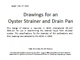
Oyster Strainer and Drain Pan This design of strainer is required in AOAC International 35107 95311 for use in determining the drained liquid from shucked oysters The specifications for the diameter of the perforations and their spacing were adopted by the AOAC in 1955 ID: 359458
Download Presentation The PPT/PDF document "Drawings for an" is the property of its rightful owner. Permission is granted to download and print the materials on this web site for personal, non-commercial use only, and to display it on your personal computer provided you do not modify the materials and that you retain all copyright notices contained in the materials. By downloading content from our website, you accept the terms of this agreement.
Slide1
Drawings for an Oyster Strainer and Drain Pan
This design of strainer is required in AOAC International 35.1.07 (953.11) for use in determining the drained liquid from shucked oysters. The specifications for the diameter of the perforations and their spacing were adopted by the AOAC in 1955.
These Drawings are Not to ScaleThis document based on a drawing (No. 1847 - August 1997) provided by the North Carolina Department of Agriculture, Division of Standards & Division of Marketing’s Engineering Program.
Issued: May 17, 2013 Slide2
AOAC Description
Apparatus:Strainer (skimmer): flat metal pan with 50.8 mm (2 inches) sides.Area: 1,900 square centimeters (300 square inches) for each 3.785 L (1 gallon) of oysters to be poured onto the pan. A smaller strainer and pan may be constructed for testing package sizes less than 3.785 L (1 gallon).Perforations and Spacing: 6 mm (1/4 inch) diameter and spaced in a 32 mm (1-1/4 inches) square pattern.
Use: Quickly distribute oysters evenly over draining surface with minimum of handling.Drain Time: 2 minutes.Temperature: 7 °C (± 1 °C) 45 °F (± 2 °F) Slide3
General Notes
Construct with 12 gage stainless steel (recommended but lighter or heavier gages are permitted). For ease of handling the weight should be kept to a minimum. The strainer and pan may be one-piece boxes with bent and welded sides or constructed entirely of plate.Containers will be used to weigh and measure food products so all welds must be watertight for ease of cleaning and to prevent the accumulation of water that may promote bacteria growth. Grind, smooth and polish all joints, and perforations.Slide4
Typical Layout of Perforations
32 mm
(1-¼ inches)
32 mm
(1- ¼ inches)
Perforation Diameter
6 mm (1/4 inch)
This Drawing Not to Scale
Locate Hole Grid on Center Line (C
L
) of strainer (see next page). For a strainer with given dimensions there will be 13 holes per row and 13 rows. For strainers of other dimensions the number of holes per row and number or rows will vary.
Perforation Diameter: 6 mm (1/4 inch).
Spacing: a 32 mm
(1-1/4 inches) square pattern as show in the detail to left.Slide5
Strainer Plan View
444.5 mm (17-1/2 inches)
Provide Handle Each Side
(see next page for handle details)
0
0
0
0
0
0
0
0
0
0
0
0
0
444.5 mm (17-1/2 inches)
C
L
This Drawing Not to Scale
Locate Hole Grid on Center Lines (C
L
) of Strainer
C
LSlide6
Strainer End View
50.8 mm (2 inches)
Provide Handle Each SideAttach handle at 25.4 mm (1 inch) from bottom of strainer. See left of this page for details
444.5 mm (17-1/2 inches)
This Drawing is Not to Scale
Strainer Side View
444.5 mm (17-1/2 inches)
Typical Handle
12.7 mm (1/2 inch) Fillet
127 mm (5 inches)
50.8 mm (2 inches) Slide7
Pan Plan View
457.2 mm (18 inches)
Provide Handle Each Side
(see next page for handle details)
457.2 mm (18 inches)
This Drawing is Not to Scale
Solid Bottom in Pan.
Provide stainless steel bars in each corner of the drain pan to hold the strainer while it drains. Bars are attached with a continuous weld on all sides and joints.
Each bar is 19 mm x 19 mm x 63.5 mm
(¾ inch x ¾ inch x 2½ inches)Slide8
Bottom Drain Pan End View
50.8 mm (2 inches)
Provide Handle Each Side
Attach handle at 50.8 mm (2 inches) from bottom of drain pan. See above for details.
This Drawing is Not to Scale
Bottom
Drain Pan
Side View
Typical Handle
12.7 mm (1/2 inch) Fillet
127 mm (5 inches)
76.2 mm (3 inches)
457.2 mm (18 inches)
Provide stainless steel bars in each corner of the drain pan to hold the strainer while it drains. Bars are attached with a continuous weld on all sides and joints.
12.7 mm (1/2 inch) Typical
Grind smooth and polish all joints and exposed edges.
The bars are 19 mm x 19 mm x 63.5 mm
(¾ inch x ¾ inch x 2½ inches)