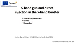
/
S-band gun and direct injection in the x-band booster S-band gun and direct injection in the x-band booster

S-band gun and direct injection in the x-band booster - PowerPoint Presentation

layla
layla . @layla
Follow
65 views
Uploaded On 2023-11-08

S-band gun and direct injection in the x-band booster - PPT Presentation

Simulation parameters Results Discussion Mohsen Dayyani Kelisani IPMCERN and Steffen Doebert CERN CompactLight Injector Meeting 1315112019 Injector Design 262 03 30 75 262 03 ID: 1030766

gun band buncher108acc case band gun case buncher108acc bunching emittance bunch velocity 1108acc longitudinal 5108componentrf injector laser energy space

Share:

Link:

Embed:

Download Presentation from below link

Download Presentation The PPT/PDF document "S-band gun and direct injection in the x..." is the property of its rightful owner. Permission is granted to download and print the materials on this web site for personal, non-commercial use only, and to display it on your personal computer provided you do not modify the materials and that you retain all copyright notices contained in the materials. By downloading content from our website, you accept the terms of this agreement.


Presentation Transcript

1. S-band gun and direct injection in the x-band boosterSimulation parametersResultsDiscussionMohsen Dayyani Kelisani (IPM/CERN) and Steffen Doebert (CERN)CompactLight ,Injector Meeting, 13-15.11.2019

2. Injector Design2620.33.0-752620.375Laser parameters, uniform distributionsParameterRF GunBuncherAccFrequencyGradientN. CellParameterRF GunBuncherAccFrequencyGradientN. CellRF- parametersPhilosophy: Use S-band rf-gun because of its well established performance (cathode, laser, magnets) Use directly X-band for velocity bunching and acceleration INFN-type RF gun , CompactLight x-band structure usedUsing ASTRA for simulationsThermal emittance 0.08 um (copper)Relatively long initial laser pulse !

3. CompactLight requirements Beam Energy Energy SpreadRMS Bunch LengthBunch ChargeEmittancePeak Current 60 ABeam Energy Energy SpreadRMS Bunch LengthBunch ChargeEmittancePeak Current 60 ACompactLight target parameters- High repetition rate needed 100 - 1000 Hz

4. Case 1 : simply acceleration no bunchingComponentRF Gun-Buncher108Acc.1108Acc.2-5108ComponentRF Gun-Buncher108Acc.1108Acc.2-51083560.114620.111153560.114620.11115

5. Case 1 : simply acceleration no bunching3560.114620.111153560.114620.11115Nice emittance but probably to much energy spread and curvatureDifference to full x-band version, longer laser pulse due to lower gradientAll on-crest for simplicity

6. Case 2 : velocity bunching to 332 fs2970.13320.132970.13320.13ComponentRF Gun-Buncher108Acc.1108Acc.2-5108ComponentRF Gun-Buncher108Acc.1108Acc.2-5108

7. Case 2 : velocity bunching to 332 fsThis case has been used for subsequent Linac simulations by Xingguang Liu, see Helsinki workshopRelative linear phase space but somewhat asymmetric longitudinal distribution

8. Case 3 : velocity bunching to 250 fsComponentRF Gun-Buncher108Acc.1-5108ComponentRF Gun-Buncher108Acc.1-51083 ps initial laser pulse lengthLess linear phase space but more symmetric longitudinal distribution

9. Case 3 : velocity bunching to avoid first bunch compressor0.10.161620.10.16162ComponentRF Gun-Buncher108Acc.1108Acc.2-5108ComponentRF Gun-Buncher108Acc.1108Acc.2-5108Phase space and distribution is not pretty anymore, emittance still fine

10. Longitudinal phase space evolution (250 fs version)

11. Using an S-band structure for velocity bunching to compareComponentRF Gun-Buncher30Acc.1-5108ComponentRF Gun-Buncher30Acc.1-51083 ps initial laser pulse length

12. Bunch compression studies (BC1 to 50 fs)S+S+X 265 fsS+X 330 fsS+X 250 fsWhat is better at the end of the linac ?

13. Shorter solenoid section (250 fs version)Some emittance increase but still possible

14. Wake field considerationsWe don’t have the full 3D field map of the CompactLight x-band structure yetFirst analytical (worst case) look into longitudinal and transverse wake fields (350 fs case)Longitudinal wakesTransverse wakes, 50 mm (0.5 sigma) and 100 mm (1 sigma) offsetWake field effect within the injector seems quite smallComplete 3D-field map of the structure needed for more realistic simulations

15. Discussion ILike to break up the injector into piecesRF-gun: S-band has many advantages, may be most important is choice of cathodeNot critical for space, could be chosen independent from rest of injectorNeed really higher gradient for C or X band gun to profit: > 200 MV/m ? Feasible ?Some x-band experience shows difficulties for a useable gradient above 150 MV/m C-band prototype test would be essentialVelocity bunching section: All frequencies seem to work, S-band has more flexibility in choosing the phaseAcceleration part: First section critical, emittance can be preserved in all schemes, x-band offers shortest length and likely lower costbeam samples more rf curvature Seems difficult to scale bunch length and preserve emittance

16. Discussion IILooks like it comes down to the linearization problemDo we have a promising lineariser at 36 GHz or higher ?Which phase spaces are compatible with FEL operation ?ConclusionMore studies on lineariser and bunch compression in the linac needed to see if the rf curvature sampled from x-band is a problemWe will continue looking into tolerances and further optimisation for this type of injector. Need a clear optimisation criteria