/
IEEE JOURNAL OF QUANTUM ELECTRONICS VOL IEEE JOURNAL OF QUANTUM ELECTRONICS VOL

IEEE JOURNAL OF QUANTUM ELECTRONICS VOL - PDF document

liane-varnes
liane-varnes . @liane-varnes
Follow
472 views
Uploaded On 2015-01-15

IEEE JOURNAL OF QUANTUM ELECTRONICS VOL - PPT Presentation

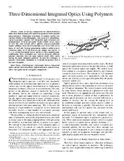
35 NO 8 AUGUST 1999 ThreeDimensional Integrated Optics Using Polymers Sean M Garner SangShin Lee Vadim Chuyanov Antao Chen Araz Yacoubian William H Steier and Larry R Dalton Abstract Some of the key components are demonstrated to make threedimen ID: 31401

AUGUST

Share:

Link:

Embed:

Download Presentation from below link

Download Pdf The PPT/PDF document "IEEE JOURNAL OF QUANTUM ELECTRONICS VOL" is the property of its rightful owner. Permission is granted to download and print the materials on this web site for personal, non-commercial use only, and to display it on your personal computer provided you do not modify the materials and that you retain all copyright notices contained in the materials. By downloading content from our website, you accept the terms of this agreement.


Presentation Transcript

IEEEJOURNALOFQUANTUMELECTRONICS,VOL.35,NO.8,AUGUST1999Three-DimensionalIntegratedOpticsUsingPolymersSeanM.Garner,Sang-ShinLee,VadimChuyanov,AntaoChen,ArazYacoubian,WilliamH.Steier,andLarryR.DaltonAbstractÐSomeofthekeycomponentsaredemonstratedtomakethree-dimensional(3-D)opticalintegratedcircuitspossibleusingpolymers.Fabricationtechniquesofshadowreactiveionetching,shadowphotolithography,andgray-levelphotolithog-raphytoproducecomplex3-Dintegratedopticstructuresaredemonstrated.Verticalwaveguidebendsexhibitexcesslosses Fig.1.Generaldesignof3-Dintegratedoptics.(Onlythewaveguidecoreisshownforclarity.)verticalwaveguideinterconnectsbetweenthelayers.Thethird 4vertical±horizontalstructure,andverticalwaveguidepo- etal.:THREE-DIMENSIONALINTEGRATEDOPTICSUSINGPOLYMERS (a) Fig.2.ShadowRIEtechniqueforslopeetching.(a)Schematicofetchingmethod.(b)Pro leoftheetchedslope.photobleachingofpolymerswhichcontainchromophorescancreateadepth-dependentindexvariation[3]andhasbeenusedtofabricatetaperedwaveguides.Replicationmethodsofembossingandmoldingallowmassproductionofintegratedopticalcomponentsandhavebeenusedforlow-costmi-crostructures[4].Thesemethods,however,arenotsuitableforconstructingverticalwaveguideinterconnectsamongmultiplelayers.Tofabricate3-Dintegratedopticalstructures,weemployedreactiveionetching(RIE)inO andCF toetchlow-angleslopesinthepolymerlayers,eitherdirectlybyshadowmasksorthroughintermediatepatternedphotoresistA.ShadowMaskReactiveIonEtching(RIE)Thisapproachofdirectlyetchingaslopeinapolymerlayerinvolvesplacingashadowmaskonthepolymersurfacebeforeplacingthesampleintothereactingchamber.Fig.2illustratesboththeshadowRIEtechniqueandatypicalslopeasmeasuredwithaSloanDektakIIApro lometer.Thepresenceofthemaskoverhangproducesavariableetchrateacrossthesurfaceofthe lm.Themasksconsistedofstandardmicroscopeslidessupportedattheedgesapproximately2mmabovethepolymerBycontrollingthegaspressure,RFpower,etchingtime,andphysicaldimensions(overhangoffsetandlength)ofthemask,predictableS-curvedverticalslopescanbeetchedbyusingcalibrationcurvesforeachparameter[5].Agoodempiricalcurve ttothestretched-SshapedslopeproducedbytheRIEetchisprovidedby[5,eq.(1)].Thehorizontalandverticalfunctioncoordinatesare and ,while and aretheoverallslopeheightandlength,respectively: Theparameters and havebeenexperimentallymeasuredforavarietyofetchconditionsin[5].Forexample,toproducesmoothlyetchedsurfacesinthepolymer lms,weusedthefollowingconditionswithatypicalparallel-plateplasmaetcher:bothO andCF gases[6]at owratesof25and10sccm,achamberpressureof400mtorr,andanRFpowerdensityof0.15W/cm .A60-minetchtypicallyyields and valuesof5.5and1.4 m,respectively.Ingeneral,moredirectionaletches(higherpressure,etc.)andlargerspacingbetweenthemaskandthesurfacetobeetchedyieldlargerslopeanglesandshorterslopelengths.Withthismethod,wehaveproducedslopeanglesrangingfrom0.1 to3 withetchdepthsofupto15 m.Thisetchdepthwaslimitedonlybythethicknessofthepolymer lms.Slopelengthstypicallyrangedfrom0.1to2mm.Thiswidevarietyoftaperdimensionsenablesfastprototypingofnew3-Ddevicedesigns,anditavoidstime-consumingphotolithographysteps.B.PartialExposurePhotolithographyAnothermethodforproducingverticalstructuresinpoly-mersinvolves rstcreating3-DfeaturesinaphotoresistoverlayerandthentransferringthemwithstandardRIEtech-niquestotheunderlyingpolymer lm.Toproducetheverticalfeatures,the rststepreliesonthepartialexposureofthepho-toresisteitherbyshadowlithographyorgray-levellithographyandsubsequentdevelopmentofthephotoresist.TheverticalfeatureinthephotoresistcanbetransferredtotheunderlyingopticalpolymerlayerbyRIEbecausetheopticalpolymersandphotoresisthavesimilaretchrates,typicallyrangingfrom0.03to0.12 m/min.Insomecases,thereisaslightdifferenceinetchrateswhichenableexpandingorcontractingtheverticalfeatureswhiletransferringthemtotheopticalpolymers.Inthistechnique,thephotoresistlayermustbeasthickasorthickerthantheverticalheightoftheslopebeingtransferred.WeusedphotoresistAZ5214E(HoeschtCelanese)for lmthicknessesofupto3.5 mandAZP4620for lmsupto6 m.Fordeepertopographies,weeitherspunmultiplephotoresistlayersormademultipleprocessingcycles.Tofullydevelopthesethickphotoresistlayersrequiressomeagitationwhileinthedevelopersolution.Theverticalfeaturesinthephotoresistcanbeperiodicallymeasuredandpreciselycontrolledbeforepermanentlyetchingtheopticalpolymer.SincetheslopecharacteristicsdependonboththeexposureanddevelopmenttimeswitheitherAZ400KorAZ421Kdevelopers,thefeaturedimensionscanbe netunedafterDektakmeasurements.Iftheopticalpolymeriscrosslinkedorotherwisehardenedtoberesistanttosolvents,misalignedorpoor-qualityphotoresistpatternscanbeeasilyremovedandtheprocessrepeated.Finally,theuseofastandardmaskaligner(KarlSuss-MJB3)allowsprecisioninboththealignmentandexposureofthephotoresistpatterns.Useofeithertheshadoworgray-levelphotolithographymask,describedbelow,produceshigh-qualityverticalphotoresist1)ShadowPhotolithography:Shadowphotolithographyconsistsofusingastandardstraight-edgemaskpattern,verticallyoffsetfromthesample,toproduceavariableexposureoftheunderlyingphotoresist.Fig.3(a)illustratesthistechnique.Thevariableexposureisduetothediffractionandre ectionsoftheultraviolet(UV)light.Fig.3(b)shows IEEEJOURNALOFQUANTUMELECTRONICS,VOL.35,NO.8,AUGUST1999 (a) Fig.3.Shadowphotolithographytechniqueforslopeetching.(a)Schematicofetchingmethod.(b)Pro leofetchedslope. Fig.4.Controlofslopeanglesusingshadowphotolithography.Measuredslopeangleasafunctionofmaskalignerexposingenergydensity.Datashownfortwophotoresistthicknesses,atypicalslopeproduced.Ithasaheightof4 mandalengthof20 m.Becauseofthecollimatedlightfromthemaskalignersource,theresultingslopespossesslargeanglesrangingfrom1 to13 inphotoresistthicknessesofupto m.Forthistechnique,wetypicallyusedtheAZ5214Ephotoresistbecauseoftheshorterexposuretimesitrequired.Theresultingverticalslopedependsontheexposingenergydensity,photoresistthickness,andmaskverticaloffset.Vary-inganyoftheseparametersallowscontroloftheslopeangle,andthisexposureprocessmustbecalibrated.Fig.4showsthedependenceofslopeangleonexposingenergydensityforphotoresistthicknessesof3.5and4.2 m.Aconstantmaskverticaloffsetof600 mwasused.Withanexposingpowerdensityof5mW/cm ,weeasilyproducedawiderangeofrepeatableanglesbyvaryingtheexposingtimefrom1to2min.Becauseshadowphotolithographyproducesavarietyofangleswithasinglemask,itenablesfastprototypingofnewdevicedesigns.2)Gray-LevelPhotolithography:Gray-levelphotolithog-raphyconsistsofusingavariabletransmissionmasktopartiallyexposethephotoresist.Fig.5(a)illustratesthismethod.Theposition-dependenttransmissionofthemaskproducesthevariableUVexposureofthephotoresist.Thistechniqueallowsthetransferofverycomplexpatternstotheentirephotoresist lmwithasingleexposure.Fig.5(b)showsatypicalslopeproduced.Ithasaheightof5.5 manda (a) Fig.5.Gray-levelphotolithographytechniqueforslopeetching.(a)Schematicofetchingmethod.(b)Pro leofetchedslope.taperlengthof100 m.Thelowerbendangleonlyappearssharpbecauseofthedifferentscalesofthetwoaxes.Usingthismethod,weproducedslopeanglesrangingfrom0.1 to3 in lmthicknessesofupto15 m.Additionally,theuseofeitherAZ5214orAZP4620producedhigh-qualityslopes.Wefabricatedthetransmissionmaskbytransferringacomputer-generatedgray-scaleimageontoaholographic lmplate(AGFA8E56HDNAH)[7].Themasksprovidedfeatureresolutionofabout10±15 mandproducedsmoothphotore-sistslopeswithtotallengthsof0.1±2mm.Thefabricationoftheselongslopelengthsdidnotrequirehigherresolutiongray-levelmasks.Alternativemasksourcesinclude:commercialfabricatingfromaspatially lteredhalf-toneimage[8],anddirectelectronbeamwritingonadosagesensitivesubstrate[9].Theadvantageofgray-levelphotolithographyliesintheabilitytocreatearbitraryandcomplexsurfacetopographiesinphotoresist lms.Fabricationof32leveldiffractiveopticalelementswithoneexposurehavebeenreported[7].Asinglecomplexmaskcouldbeusedtofabricatemanyverticalfea-turesinoneprocessingstepinthemanufacturingofcomplex3-Dopticalcircuits.C.FabricationSummaryInsummary,threespeci cmethodsexistforcreatingverti-calstructuresinopticalpolymers.TheseincludeshadowRIE,shadowphotolithography,andgray-levelphotolithography.ShadowRIEgenerallycreatessmallslopeanglesof 3 .Itdoesnotrequireanyextensiveprocessingsteps,soitisidealforprototypingnewdevicedesigns.Shadowphotolithography,ontheotherhand,generallycreateslargerslopeanglesof ±13 .Theuseofthemaskaligner,however,allowsprecisealignmentandtimingoftheexposurethatisnotpossiblewiththeRIEtechnique.Finally,gray-levelphotolithographyallowsthemostfreedominverticalstructurefabrication.Themaskalignerandtransmissionofthegray-levelmaskenableprecisecontrolofthedevelopedphotoresistfeatures.AlthoughtheySee,forexample,SinePatternsLLC,EastRochester,NY. etal.:THREE-DIMENSIONALINTEGRATEDOPTICSUSINGPOLYMERSoffervaryingdegreesofprocessingcontrol,eachofthethreefabricationtechniquesenableverticalstructuresforpractical3-Dintegratedoptics.Therestofthispaperdiscussesafewrepresentativeandkeyopticalelementsforthe3-Dintegrationofopticalwaveguidedevices.III.APPLICATIONSOF3-DSTheabilitytofabricateverticalfeatures,particularlygentleverticalslopes,makespossiblethekeyelementstorealizecomplex3-Dintegratedoptics.Thekeysingle-modeelementsthatwehavedemonstratedareverticalwaveguidebends,powersplitters,andpolarizationsplitterstoprovideroutingoftheopticalpowerbetweenmultipleverticallevels.Wehavealsodemonstratedtheintegrationofpolymerelectroopticswitchesandmodulatorswithpassivepolymerintegratedopticsusingthe3-Dapproach.Inallofthesestructures,additionallayersmustbespunontopoftheverticallypatternedslopestomaketheupperwaveguidinglayers.Forslopeanglesofafewdegrees,spincastingadditional lmsof 5- mthicknessespreservestheoriginalsurfacecontour.Thicker lmsorsteeperanglescauseaplanarizationeffectofthesurfacefeatureswhichmustbetakenintoaccountinthedevicedesign.A.VerticalWaveguideBendsSimilartothe2-Dcase,verticalwaveguidebendsareanecessarycomponentforpractical3-Dintegratedopticsforthelow-losstransferofpowerbetweenthelayers.Verticaldirectionalcouplers[10]havepreviouslybeenusedtotransferpowerbetweendifferentwaveguidecores.Thesedevices,however,areverysensitivetowavelengthandfabricationtolerancesofthewaveguidedimensions.Thedesignandfabricationoftheverticalwaveguidebendsdescribedbelowprovidesthebasisformorecomplicatedstructuressuchasverticalpowerandpolarizationsplitters.1)Fabrication:Thefabricationofverticalwaveguidebendsinvolved rstspincastingan11- mUV15LV(MasterBond)lowercladdinglayerontoaSisubstrate.Thisthicknessrequiredtwosubsequentspinning/curingcycles.Toachievehigh-quality lms,theUV15LVmustpassthrougha0.2- lterbeforespincasting.Next,a1.6 slopewithaheightof3.0 mwasetchedacrosshalfofthesamplewiththemethodsdescribedinSectionII.The nalstepsincludedspincastinga2.0- mNOA-73(Norland)guidinglayer,etchingawaveguidewitha0.3- mridge,andthenspincastinganadditional4.6- mUV15LVuppercladdinglayer.All lmswereUVcured.Thiscreatesstandardstraightwaveguidesandverticalwaveguidebendsonthesamesamplewithwaveguidewidthsvaryingfrom1to6 m.Forthecoreandcladdingmaterials,therefractiveindicesat mare1.542and1.510,respectively.Cuttingthesampleswithadicingsawtoalengthof1cmprovidedhigh-qualityendfacesfor bercoupling.Fig.6illustratesthewaveguidebendtestsample.2)ExperimentalResults:Toevaluatetheverticalwave-guidebends,polarizedlight( m)fromastandardsingle-modeoptical berwaslaunchedintothewaveguide.Theoutputwascollectedwitha60 microscopeobjective Fig.6.Verticalwaveguidebendtestsample.Three-dimensionalwaveguidebendsfabricatedadjacenttostraightwaveguides.(Onlythewaveguidecoreisshownforclarity.) Fig.7.Propagationlossasafunctionoflengthforaslabverticalwaveguidebendatm.(Discontinuitycorrespondstoverticalslopeposition.)lensandfocusedontoacalibrateddetector.Comparingtheoutputpoweroftheverticalwaveguidebendswiththeadjacentstraightwaveguidesdemonstratedanexcesslossvalueaslowas0.2dB.Excesslossisde nedastheratioofthepoweroutofaverticalbendwaveguidetothatofanadjacentstraightwaveguideusingthesamelightinputandoutputconditionsasmuchaspossible.Theaccuracyofthismeasurementdependsontherepeatabilityoftheinputandoutputconditionsandisestimatedtobe0.1dB.Wewereabletocon rmthislowexcesslossforsimilarlyfabricatedslabwaveguidebendsbyusingtheliquidout-couplingmeasurementtechniquedevelopedbyTeng[11].Inthismethod,lightiscoupledintoaslabmodeandisoutcoupledatthesurfaceofahighindexliquidasthesampleisimmersedintheliquid.Theslopeofaplotoftheoutputpowerasafunctionofthedepthofimmersiongivesthepropagationloss,whichisindependentoftheinputcouplingef ciency.Fig.7showsthisplotforaslabwaveguidewithaverticalbend.The0.5-dBdiscontinuityinthepropagationlosscorrespondstothepositionoftheverticalbend.Theaccuracyofthismeasurementislimitedbythelinearcurve ttingofthepower uctuations.Typically,thiserrorisestimatedtobe0.3dB.Fig.8showstheTEandTMpolarizationinsertionlossesforvariouswaveguidewidths.Theseinsertionlossesinclude bercouplingattheinput,materialloss,andpropagationlossinthewaveguide.Weobservedlossesindependentofboththepolarizationandpropagationdirection.Allwaveguidesweredesignedtobesinglemodeat1.31 m.Finally,viewingthewaveguidepatternswithascanningelectronmicroscopeshowedhigh-qualityphotolithographyde nitionthroughoutthestructureeventhoughthelevelsdiffersubstantiallyin IEEEJOURNALOFQUANTUMELECTRONICS,VOL.35,NO.8,AUGUST1999 (a) Fig.8.Insertionlossforverticalwaveguidebendsandstraightwaveguidesm(allwaveguidesare1cminlength).(a)TEpolarization.(b)TMpolarization.verticalheight.Two-dimensionalbeampropagationsimula-tions(RSoft)predictedradiationlossesofonly0.05dBwhenrepresentingthebendasacosineS-curve[12],[13].Wethereforesuspectthatthemeasuredexcesslossesaredominatedbyscatteringlosswhichcouldpossiblybereducedbyimprovementsintheetchingprocedure.Theverticalbendsarecharacterizedbytherelativelylargeindexdifferencebetweenthecoreandthecladding,typically 0.03.Becauseofthelargeverticalindexdifference,theverticalbendscanhavemuchsmallerturningradiithanischaracteristicofhorizontalbendswhenthehorizontalpattern-ingisdonewithridgewaveguides.Forexample,tomovethemodeup5 minaverticalbendrequiredonlya110- mtransitionlength.Thesmallerhorizontaleffectiveindexdifference,however,requiresatotalbendlengthof 1600 mtohorizontallydisplacetheopticalmodethesamerelativedistancewithanequivalentradiationloss.B.VerticalPowerSplittersAnalogoustoasymmetricY-branches,verticalpowersplit-tersdividetheopticalpoweramongmultipleverticallayers.Theirdesignconsistsofoptimizingthecouplingoftheinputopticalmodetothemodesoftheoutputwaveguides,main-tainingtheopticalisolationoftheoutputs,andreducingtheradiationlosswithinthebranchingregion.Todividetheopticalpowerarbitrarilyamongtheoutputwaveguides,thesplittermustactasanonadiabaticdevice.Nonadiabaticstructuresarecharacterizedbyrelativelylargebranchingangles.Theresultisthattheratiooftheoutputopti-calpowersdependsonthedifferenceinpropagationconstantsofthetwooutputwaveguidesandtheincorporatedbranchangle[14].Incontrast,adiabaticdeviceshaverelativelysmallbranchinganglesandtheinputpoweriscoupledcompletely Fig.9.AsymmetricY-branchdesignforverticalpowersplitter.Theoutputpowersplittingratiodependsonthepropagationconstantsforthebranchwaveguidesandthebranchingangletotheoutputbranchwhosepropagationconstantmostnearlymatchesthatoftheinputwaveguide[14].Theverticalpowersplitterswehavefabricatedarenona-diabatic,andthepowersplittingratioiscontrolledbythepropagationconstantsofthetwosingle-modeoutputwaveg-uides.Duringfabrication,thesearecontrolledbyvaryingthespincast lmthicknesses.ForaY-branchtohaveequalpoweroutputs,theinputmodemustcoupleequallytothesuper-modesofthebranchingregion.Forsymmetricstructureswheretheoutputshavethesamecouplingangle,thisrequiresequaleffectiveindicesinthetwobrancharms.ForasymmetricY-branchesasshowninFig.9,however,adifferenceinthepropagationconstantsmustcompensateforthegeometricasymmetrypresent.Todeterminethepowersplittingdependenceonthebranch-ingangleandpropagationconstants,weperformed2-Dbeampropagationsimulations.Wevariedtheangleandpropagationconstantsbychangingthetransitionlengthandwaveguidethicknesses,respectively.Inthefabricationprocedurede-scribedinSectionIII-B1,theinputandtheupperoutputwaveguideshavethesamethickness.Wethereforemadethatassumptioninouranalysis.Theindexvaluesusedcorre-spondedtoUV15LVandNOA-73,andtheoutputwaveguideseparationwasaconstant10 m.ThecontourplotsinFig.10showthesplittingratio,whichisde nedastheoutputpowerratiooftheuppertolowerwaveguides,asafunctionofbranchingangleandupperwaveguidethickness.Ineachplot,thelowerwaveguidethicknessisheldtoitsinitialvalue.Fromthecontourplots,threedesignfeaturesbecomeappar-ent.Firstofall,comparingthethreeplotsshowsthatahighertoleranceforfabricationerrorsexistsinthethickerwaveguidedesigns.Asthewaveguidethicknessincreases,theareaforeachsplittingvalue( 10%)becomeslarger.Second,3-dBpowersplitterspossessanoptimumbranchinganglevaluefor xedwaveguidedimensions.Forlargerangles,theinputmodepredominantlycouplestothelowerwaveguidebecauseofthegeometricalasymmetryandhigherradiationlossintheupperbranch.Forsmallerangles,themodeadiabaticallyselectstheoutputwithahighereffectiveindex.Finally,changingtheupperwaveguidethicknessvariesthepowersplittingratiobyaffectingthedifferenceinwaveguideeffectivein-dices.Therefore, neadjustmentsofthetransitionlengthandwaveguidethicknessesallowcontroloftheverticalpower etal.:THREE-DIMENSIONALINTEGRATEDOPTICSUSINGPOLYMERS (a) (b) Fig.10.Y-branchpowersplittingratioasafunctionofupperbranchwaveguidethicknessandranchingangle.Lowerbranchwaveguidethicknessheldtotheconstantvalueindicatedforeachgraph.Thecontourlabelsindicatethepowersplittingratiovalues.(a)2-mlowerwaveguidethickness.(b)3-lowerwaveguidethickness.(c)4-mlowerwaveguidethickness.splittingratiothroughawiderangeofvalues.Waveguidethicknessescloseto3 mprovidethebestperformancecontrolwhenconsideringpracticalspincastthicknessesandmodeMaintainingopticalisolationoftheoutputwaveguides,anotherdesignconsideration,requiresaminimumthicknessoftheintermediatecladdinglayer.FortheUV15LVandNOA-73indexvalues,waveguidethicknessesof3 m,outputwaveguidelengthsof1cm,anda6.5- mverticalwaveguideseparationyieldsanisolationbetweentheoutputsof 30dB.Finally,verticalpowersplittersmustminimizeradiationloss.Themajorsourceofradiationlossistypicallytheradiationintothewaveguideslabmodesinthebranchingregion.Inthisregion,thewaveguideverticalthicknessbe-comesgreaterwhiletheridgeheightremainsconstant;thisreducesthehorizontalcon nementandincreasesthecouplingtotheslabmodes.Topreventthis,wedesignedadualridge/channelwaveguidestructurewhichmaximizesopticalcon nementthroughoutthestructure.Fig.11illustratesthedualridge/channelstructureandalsoshowscorecrosssections Fig.11.Verticalpowersplitterschematicandcorecrosssections.Crosssectionsshowthetransformationoftheinputridgewaveguideintoadualridge/channeloutputstructurewithhighmodalcon nement.(Onlythewave-guidecoreisshownforclarity.)withinthebranchingregion.Thepresenceofboththeridgeandthechanneloftheupperandlowerwaveguidesinthejunctionallowsthecoreslabregiontoverticallyexpandwhilemaintainingthesameamountofhorizontalcon nement.Experimentalresultsshownlatersupportthisconclusion.1)Fabrication:FabricationofverticalpowersplittersisillustratedinFig.12.The rststepinvolvespatterningaAu-coatedSiwaferwiththehorizontalwaveguidepatterntoprovidethenecessarymarksforaligningtheverticallystackedwaveguides.Thisallowshorizontalalignmentofthewaveguidesonmultipleverticallevelswithin 2 m.Next,a9.5- mUV15LVlowercladdingwasspun,and0.6- deep,6- m-widechannelwaveguidepatternswereetched.AfterspincastingNOA-73fora3.1- mlowercorethickness[Fig.12(a)]anda9.5- mUV15LVintermediatecladdinglayer,a0.5 slopewithadepthof12.6 mwasetcheddownthroughthede nedlowerchannel[Fig.12(b)].Wecontrolledtheetchdepthbymonitoringthe lmthicknessinaportionoftheetchedregion.Basedonmonitoredlowercoreandslopedimensions,theuppercorethicknessnecessaryfora3-dBpowersplitterwasdeterminedfromthecomputeranalysis.Finally,a3.2- muppercorewasspincastanda0.4- mupperridgewaveguidepatternetchedintothe lm[Fig.12(c)].Thistransformsthesingle-ridgewaveguideinputintoadualsingle-moderidge/channeloutputstructure,anditcausestheinputanduppercorewaveguidestohavethesamethickness.All lmswereUVcured.The nalstepsincludespincastinga muppercladdinglayerandcuttingtheendfaceswithadicingsawtoalengthof1.5cm.2)ExperimentalResults:Toevaluatetheverticalpowersplitterweusedthesameexperimentalsetupasthatfortheverticalbends.Launchinglightintothesinglewave-guideendshowedsingle-modeperformanceofthetwooutputwaveguides.Likewise,launchinglightintoeitherofthetwobranchwaveguidesexcitedonlyasinglemodeofthebasewaveguide.Fig.13showstheoutputpatternfromeachofthestructureends.Addingtheoutputpowerofthetwobranchwaveguidesshowedaninsertionlossof4.0 dB.Similarlyfabricatedstraight2-Dwaveguidesresultedininsertionlossesof4.0 0.2dB.Theseinsertionlossesincludeinput bercoupling,waveguidepropagation,andexcesslossduetotheverticalslope.Comparingtheseinsertionlossvaluesgivesanindicationoftheexcesslossduetotheverticalsplitting.Thislowexcesslossof 0.3dBexistedforboth IEEEJOURNALOFQUANTUMELECTRONICS,VOL.35,NO.8,AUGUST1999 (a)(b)(c)Fig.12.Fabricationprocedureofverticalpowersplitters.(a)Channelwaveguidede nedinlowercladdingandcore.(b)Middlecladdingspincastanverticalslopeetcheddownthroughlowercorelayer.(c)Uppercorespincastandridgewaveguidede nedthroughoutstructure. (a) Fig.13.Verticalpowersplitteroutputpatternsfor3-D12structureatm.(a)Singlewaveguideendoutput.Lightlaunchedintoeitherbranchwaveguide.(b)Dualwaveguidebranchedoutput.Lightlaunchedintosinglebasewaveguide.polarizations.Additionally,weobservednoscatteringfromabovewithaninfraredcamerawhenlaunching40mWintothewaveguides.Furthermore,performancedidnotdegradefor m-widewaveguideshorizontallymisalignedbyupto2 ascanbeseenfromtheoutputpatternofFig.13(b).Wemeasuredthepowersplittingratio(theratioofthepowerfromtheupperwaveguidetothatfromthelower)byfocusingtheoutputpatternonadetector50cmawayandusingaknifeedgetoblocktheoutputfromeithertheupperorlowerwaveguidecores.Wemeasuredtheoutputpowerratiotobe1.6 0.3.Simulationsbasedonmonitoredfabricationdimensionspredictedasplittingratioof1:1.Thedeviationfromtheexpectedoutputratiomayresultfromuncertaintyinthecorethicknesses,uncertaintyinthebranchingangle,andfromthedifferentphotolithographyandetchingconditionsthateachoutputbrancharmmayexperience.Tightercontrolofthefabricationconditionsshouldimprovethepredictability.VerticallystackingtwohorizontalY-branchesresultedina3-D1 4splitter.Thesingle-basewaveguide rstbranchedverticallyandthen,immediately,horizontallytoproducethefourbranchwaveguides.Fig.14showsthedeviceandtheoutputpatternsforboththesingleandbranchedwaveguide (a) (b)(c)Fig.14.Three-dimensional14powersplitterwaveguidedesignandoutputpatternatm.(a)14powersplitterdesignincorporatingoneverticalbranchandtwohorizontalY-branches.(Onlythewaveguidecoreisshownforclarity.)(b)Singlewaveguideendoutput.Lightlaunchedintoanyofthefourbranchwaveguides.(c)Branchedwaveguideendoutput.Lightlaunchedintosinglebasewaveguide.endsofthestructure.Combiningthemeasuredbranchoutputpowersshowedinsertionlossesof4.8 0.1dB.Forcom-parison,similarlyfabricated2-D1 2horizontalY-branchesresultedininsertionlossesof4.3 0.6dB.Thisincreasedinsertionlossofthe3-Dsplitterisduetotheextrawaveguidebranchingintheverticaldirection.Thefabricated1 splittershadpowervariationsamongthe4outputwaveguidesof33%.Zerovariationcorrespondstoa1 4splitterwithequalpowerinalloutputs.Asmeasuredinthefabricated2-D 2Y-branches,horizontalsplittingresultsinoutputpowervariationsof12%.Theslightlyincreasedinsertionlossandpowervariationofthe3-D1 4splittersmayresultfromradiationlossduetothecloseproximityoftheverticalandhorizontalwaveguidebranches,andthesemaybereducedwithlongerdevicelengths.Itisimportanttoconsiderhowfabricationerrorsaffectthepredictabilityofthepowersplittingratio.Theerrorscanbeinthebranchwaveguidede nition(thicknessandridge/channelheight)whichvariestheeffectiveindexoftheoutputguides,andtheerrorscanalsooccurintheslopede nition.From etal.:THREE-DIMENSIONALINTEGRATEDOPTICSUSINGPOLYMERSrepeatedmeasurements,webelievetheerrorsin lmthicknessandridge/channelheightcanbeheldto 0.1 m,andthevariationintheindexofrefractionofthepolymersistypically 10 .Fromabeampropagationanalysis,theseerrorscanresultina 13%variationinthepowersplittingratio.Thelargestsourceofthevariationisduetotherelativethicknessandridge/channelheightvariationoftheoutputwaveguides.Intheetchingoftheslope,boththeslopeangleanddepthoftheetchcouldvaryfromtheexpectedvalue.VariationsinslopeangleoccurduetoRIEorphotolithographyrepeata-bilitieswhenprocessing 10- mfeatureheights.Fromourmeasurements,anglestypicallyfallwithin 15%ofthetargetvalueandetchdeptherrorsare 0.1 m.Basedonabeampropagationanalysis,theseerrorscanresultina 7%variationinthepowersplitting,withthelargestvariationduetoslopeangleerrors.Theverticaldepthfabricationerrorinde ningthesloperesultsinavariationoftheinputbasewaveguidethickness.Theslighteffectthisthicknesshasonthepowersplittingperformanceallowstheverticalpowersplitterstobebuiltwithouttheneedforanetchstop[15].Itmaybepossible,duringthefabricationprocess,tocom-pensateforaccumulatederrorsinthelowercoreorslopede nitionbytheappropriateadjustmentoftheuppercoredimensions.These lmthicknessorslopeangleerrorscanbedetectedusingthepro lometer.Also,incorporationofbleach-ablechromophoresshouldallowinsitutrimmingofdeviceperformanceinawaysimilarto2-Dstructures[16],[17].C.VerticalPolarizationSplittersPolarizationsplittersareusedtoseparatetheorthogonalpolarizationcomponentsoftheguidedwaves.Theseareessen-tialcomponentsforcoherentreceiversand ltersemployingapolarizationdiversitydesign.Three-dimensionalintegrationmay ndapplicationinthesesystemstoreducethesubstratesizerequiredandaverticalpolarizationsplitterwouldbeakeycomponent.1)Design:Thedesignofverticalpolarizationsplitters[19]followscloselythatofthedevicesdescribedpreviously,buttheyrelyonthebirefringencesobtainableinpolymerstocreateapolarizationdependentsplitting.Fig.15(a)illustratesthisdevice.Itsoperationisbasedontheadiabatictransformationinthejunction.TheTEmodethenpropagatestotheoutputwiththehighestTEeffectiveindex,andtheTMmodepropagatestotheoutputwiththehighestTMeffectiveindex.Commerciallyavailablebirefringentandisotropicpolymerscreatetherequiredpolarization-dependentdifferenceinef-fectiveindex.ThebirefringentpolyimidesUltradel9020Dand7501(Amoco)composedthelowercladdingandcore,respectively.TheisotropicUV15LVandNOA-73madeuptheremainingcladdingandcorelayers,respectively.At m,9020Dhasanindexvalueof1.522and1.495forTEandTMmodes,respectively.7501hasindexvaluesof1.562and1.526forTEandTMpolarizations.Beampropagationsimulationsdeterminedtheoptimumwaveguidedimensionsandbranchingangle.Thefabricationprocesswassimilartothatfortheverticalpowersplitter.In[18],thedetailsofthedesign,fabricationprocedure,andamorecompleteanalysisoftheverticalpolarizationsplitterarereported. (a) (b)(c)(d)Fig.15.Verticalpolarizationsplitterdesignandoutputs.Alloutputpatternshavelightlaunchedintosinglebasewaveguideatm.(a)Generalwaveguidestructure.Polarizationextinctionratiodependsonwaveguidebirefringenceandbranchingangle.(Onlythewaveguidecoreisshownforclarity.)(b)OutputpatternwithanalyzersetforTEpolarization.(c)OutputpatternwithanalyzersetforequalTEandTMpolarizations.(d)OutputpatternwithanalyzersetforTMpolarization.2)ExperimentalResults:Lightat m,polarizedwithequalpowerintheTEandTMmodes,wascoupledintotheinputfromastandardoptical ber.Theoutputpassedthroughapolarizerwitha50-dBextinctionandcollectedbya microscopeobjectivelensontothedetector.TheTEandTMcrosstalk,de nedastheratioofthepowerintheexpectedpolarizationatanoutputtothepowerofthatpolarizationintheoppositeoutput,were17 5dBand13 4dB,respectively.Todemonstratethesingle-modeperformanceofthesplitter,wefocusedtheoutputpatternontoascreenandvieweditwithaninfraredcamera.Fig.15(b)±(d)showstheoutputwithdifferentanalyzersettings.TheTEmodeoutputisfromthelowerwaveguide,andtheTMisfromtheupperwaveguide.Weobservednohigherordermodeswhilevaryingthelaunchconditionsoftheinput ber.D.3-DIntegrationofActiveandPassivePolymerDevicesOneoftheadvantagesofopticalpolymertechnologyistheabilitytousedifferenttypesofpolymerswithinthesameintegratedopticalcircuittoperformspeci cfunctions.Forexample,electroopticpolymersorlightamplifyingpolymerscouldbeintegratedwithlowlosspassivepolymerswhichprovidethelowlossinterconnections.Oneexampleofthisistheintegrationofahighspeedelectro-opticpolymermodulatorwithaDragonewavelengthmultiplexer[19]fabricatedfrompassivepolymermaterials.Whiletheadhesionandpatterningproblemscansometimesbedif cult,thegreatestdif cultyisofteninachievinganopticalmodematchbetweenthewaveguidesmadefromdifferentpolymers[20].The3-Dconceptprovidesapromisingmethodtointegratedifferentpolymerswhileeasilysolvingthemodematchproblem.In IEEEJOURNALOFQUANTUMELECTRONICS,VOL.35,NO.8,AUGUST1999 Fig.16.Polymerelectroopticmodulatorintegratedontopoflow-losspas-sivepolymerwaveguide.(Claddinglayersarenotshownforclarity.)thisapproach,theinterconnectwaveguidepatternis rstfabricatedinalow-losspassivepolymersystem.Theactivepolymeristhenplacedontopofthislayerandpatternedintotheareawhereneeded.Verticalcouplingstructuresarethenfabricatedtochannelthelightupintotheactivepolymerandthenbackdownagainintothepassivewaveguides.Thestructuresdiscussedpreviouslyprovidethree-dimensionalroutingtotransferthebeambetweenthepassiveandactivepolymerlayers.Todemonstratethefeasibilityoftheapproach,wehaveintegratedapoledpolymermodulatorwithpassivepolymerwaveguides.1)Design:ThedesignofthepolymermodulatorintegratedontopofapassivewaveguideisshowninFig.16.Theuppercladdingimmediatelybelowtheupperelectrodeandthelowercladdingbelowthelowerelectrodearenotshownforclarity.Thepassivewaveguidewasdesignedtoprovideaclosemodematchtothestandard8- mcore berandfor bercoupling.Theetchedverticaltaperwasdesignedtoadiabaticallycouplelighttothehigherindexuppercorelayerwhichismadeofapoledelectroopticpolymer.Voltageappliedtotheelectrodeswillphasemodulatethelightor,ifcon guredasaMach±Zehnderinterferometer,willamplitudemodulatethelight.Inthemodulatorsection,thepassivecorelayerservesasthemodulatorlowercladding.Aftermodulation,thepoweragaintransferstothepassivecoreforfurtherrouting.Boththeadiabaticslopesandthelowerelectrodeserveasinherentmode ltersinthedesigntominimizestraylightthatexistsinthedevice.Whilethemodeinthepassivewaveguidewasdesignedtobesymmetricforgood bercoupling,themodeinthemodulatorwasdesignedtobetightlycon nedtotheactivelayerforgoodmodulatoref ciency.In[21],thedesignconsiderationsandfabricationprocedurearereportedindetail.Fig.17(a)showsthe naldevicedimensionsandscaledcrosssectionsofthepassiveandactivewaveguidesegments.ThepassivecoreandcladdinglayersconsistedofNOA-73andUV15LV,respectively.Polyurethanecontainingatricyanochromophore[22]composedtheactiveuppercore.Thepolyurethanelayerwaspoledbyanelectric eldtoobtaintheelectroopticeffect.The6.5-cm-longdeviceswerefabricatedon3-inSiwafersasasubstrate.Thepassivecorewaveguidesinbothsectionsweredesignedtobesinglemodeat1.31 2)ExperimentalDemonstration:Anelectroopticphasemodulatorintegratedontopofapassivewaveguidewasdemonstratedat m.Theinputlightwasbutt (a) Fig.17.Integratedmodulatordimensionsandopticaloutput.(a)Schematicandscaledcrosssectionsofpassiveandactivewaveguidesegments.(b)Opticaloutputpatternwhenlightlaunchedintopassivewaveguidecoreatcoupledfroma berintothelowerwaveguideandcontainedequalamountsofTEandTMpolarization.Thenearcircularmodeoutputpro lefromthelowerwaveguideisshowninFig.17(b).Thepolarizationoftheoutputwasmodulatedbylow-frequencysignalsappliedtotheelectrodesandthemodulationdetectedbyviewingtheoutputthroughacrossedpolarizer.Themodulationmeasuredcorrespondedtoanelectroopticcoef cientof pm/V.Boththecontrastobservedinthemodulationandtheinsertionlossofthedeviceindicatedthatessentiallyallofthetransmittedlightcoupledupintothemodulatorandbackdownagain.Anylightthatremainedinthelowerwaveguideishighlyattenuatedbythelowermetalelectrode.Wealsomeasuredtheinsertionlossofseveralsampleswithdifferentlengthsofpassiveandactivewaveguideregions.Estimatingthelossesinthepassiveandactivematerialtobe0.5and1.5dB/cm,respectively,wewereagainabletocon rmthatthelightcouplesalmostentirelyupintotheelectroopticpolymeranddownagain.Also,fromtheknownpropagationlossesinthepassiveandactivematerials,wewereabletoestimatethelossinthetransitionregiontobe 1dB.Frombeampropagationstudies,weexpecttheradiationlossesinthetaperstobesmalland,therefore,believethelossisduetoscatteringfromthesurfaceroughnessoftheetch.Betterfabricationtechniquesshouldreducethislosssigni cantly.IV.CThisresearchshowsthat3-Dintegratedopticsinpolymercanbeaviableapproachtosigni cantlyincreasingthedensityofintegratedoptics.Therecouldbenumerousapplications etal.:THREE-DIMENSIONALINTEGRATEDOPTICSUSINGPOLYMERSforwhichthesubstrateareaislimitedand3-Dcircuitsareadvantageous.Thethirddimensionmakesastreet±avenuetypeofinterconnectionpatternpossiblewithoutcrosstalkwhentheorthogonalstreetandavenuewaveguidescross.Thiscouldmakeintegratedopticscompetitivewithfreespaceopticsforadenseopticalinterconnectionnetwork.Perhapsequallyimportant,the3-Dconceptsinvestigatedheremakeitpossibletointegratediversepolymermaterials,bothactiveandpassive,intoanopticalcircuitinawaythatsolvesthedif cultimpedanceandmode-matchingproblem.Whilethemeasuredlossesintheverticaltransitionstructuresarenotaslowastheverylowvaluespredictedinthebeampropagationsimulations,theyarelowenoughtomakeusbelievethatthelossisnotcausedbyanyinherent awintheconceptordesign.Instead,theyareprobablyduetofabricationerrorsandscatteringwhichcouldbecorrectedwithtightercontrolandbetterengineeringofthefabricationprocess.[1]L.J.Camp,R.Sharma,andM.R.Feldman,ªGuided-waveandfree-spaceopticalinterconnectsforparallel-processingsystemsacom-Appl.Opt.,vol.33,pp.6168±6180,1994.[2]R.A.Norwood,R.Blomquist,L.Eldada,C.Glass,C.Poga,L.W.Shacklette,B.Xu,S.Yin,andJ.T.Yardley,ªPolymerintegratedopticaldevicesfortelecommunicationsapplications,ºinPolymerPhotonic,B.KippelenandD.D.C.Bradley,Eds.,Proc.SPIE,vol.3281,pp.2±13,1998.[3]L.Palchetti,Q.Li,E.Giorgetti,D.Grando,andS.Sottini,ªPhotobleach-ingofpolydiacetylenewaveguidesacharacterizationoftheprocessandpatterningofopticalelements,ºAppl.Opt.,vol.36,pp.1204±1212,[4]M.T.Gale,L.G.Baraldi,andR.E.Kunz,ªReplicatedmicrostructuresforintegratedoptics,ºProc.SPIE,vol.2213,pp.2±10,1994.[5]A.Chen,F.I.Marti-Carrera,S.Garner,V.Chuyanov,andW.H.Steier,ªFabricationofverticaltapersinpolymerthin lmsbyoxygenreactiveionetchingwithashadowmaskforphotonicdeviceapplications,ºinOrganicThinFilmsforPhotonicsApplications,OSATech.Dig.Ser.1997,vol.14,pp.152±154.[6]P.R.AshleyandJ.S.Cites,ªElectro-opticpolymerdevicesfor ber-opticgyrosandotherapplications,ºinOrganicThinFilmsforPhotonicsApplications,OSATech.Dig.Ser.,1997,vol.14,pp.196±197.[7]T.J.SuleskiandD.C.O'Shea,ªGray-scalemasksfordiffractive-opticsfabricationÐI:Commercialslideimagers,ºAppl.Opt.,vol.34,pp.7507±7517,1995.[8]D.C.O'SheaandW.S.Rockward,ªGray-scalemasksfordiffractive-opticsfabricationÐII:Spatially lteredhalftonescreens,ºAppl.Opt.vol.34,pp.7518±7526,1995.[9]E.-B.Kley,F.Thoma,U.D.Zeitner,L.Wittig,andH.Aagedal,ªFabricationofmicroopticalsurfacepro lesbyusinggrayscaleProc.SPIE,vol.3276,pp.254±262,1998.[10]C.Wachter,Th.Hennig,Th.Bauer,A.Brauer,andW.Karthe,ªInte-gratedopticstowardthirddimension,ºinIntegratedOpticDevicesIIG.C.Righini,S.I.Naja ,andB.Jalali,Eds.,Proc.SPIE,vol.3278,pp.102±111,1998.[11]C.C.Teng,ªPrecisionmeasurementsoftheopticalattenuationpro lealongthepropagationpathinthin- lmwaveguides,ºAppl.Opt.,vol.32,pp.1051±1054,1993.[12]W.J.Minford,S.K.Korotky,andR.C.Alferness,ªLow-lossTi:LiNbOwaveguidebendsatIEEEJ.QuantumElectron.,vol.QE-18,pp.1802±1806,1982.[13]K.T.KoaiandP.L.Liu,ªModelingofTi:LiNbOdevicesÐPartII:S-shapedchannelwaveguidebends,ºJ.LightwaveTechnol.,vol.7,pp.1016±1021,1989.[14]W.K.BurnsandA.F.Milton,ªModeconversioninplanar-dielectricseparatingwaveguides,ºIEEEJ.QuantumElectron.,vol.QE-11,pp.32±39,1975.[15]S.Kalluri,M.Ziari,A.Chen,V.Chuyanov,W.H.Steier,D.Chen,B.Jalali,H.Fetterman,andL.R.Dalton,ªMonolithicintegrationofwaveguidepolymerelectroopticmodulatorsonVLSIcircuitry,ºPhoton.Technol.Lett.,vol.8,pp.644±646,1996.[16]A.Chen,V.Chuyanov,F.I.Marti-Carrera,S.Garner,W.H.Steier,S.S.H.Mao,Y.Ra,andL.R.Dalton,ªFasttrimmingofelectro-opticpolymerwaveguideY-branchesbypost-photobleachingfortuningthepowersplittingratio,ºProc.SPIE,vol.3147,pp.268±274,1997.[17]A.Chen,V.Chuyanov,F.I.Marti-Carrera,S.Garner,W.H.Steier,S.S.H.Mao,Y.Ra,L.R.Dalton,andY.Shi,ªTrimmingofpolymerwaveguideY-junctionbyrapidphotobleachingfortuningthepowersplittingratio,ºIEEEPhoton.Technol.Lett.,vol.9,pp.1499±1501,[18]S.M.Garner,V.Chuyanov,S.-S.Lee,A.Chen,W.H.Steier,andL.R.Dalton,ªVerticallyintegratedwaveguidepolarizationsplittersusingIEEEPhoton.Technol.Lett.,vol.11,pp.842±844,1999.[19]C.Dragone,ªAnopticalmultiplexerusingaplanararrangementoftwostarcouplers,ºIEEEPhoton.Technol.Lett.,vol.3,pp.812±815,[20]T.Watanabe,M.Hikita,M.Amano,Y.Shuto,andS.Tomaru,ªVerti-callystackedcouplerandseriallygraftedwaveguidehybridwaveguidestructuresformedusinganelectro-opticpolymer,ºJ.Appl.Phys.,vol.83,pp.639±649,1998.[21]S.M.Garner,V.Chuyanov,A.Chen,W.H.Steier,andL.R.Dalton,ªThree-dimensionalintegrationofpolymerelectro-opticmodulators,ºIEEE/LEOSOrganicOpticsandOptoelectronicsTopicalMeetingMonterey,CA,July1998,paperFC3.[22]F.Wang,A.S.Ren,M.He,A.W.Harper,L.R.Dalton,S.M.Garner,H.Zhang,A.Chen,andW.H.Steier,ªHighelectro-opticcoef cientfromapolymercontaininghighPolymerMaterialScienceandEngineering,vol.78,pp.42±43,1998.SeanM.Garner,photographandbiographynotavailableatthetimeofSang-ShinLee,photographandbiographynotavailableatthetimeofVadimChuyanov,photographandbiographynotavailableatthetimeofAntaoChen,photographandbiographynotavailableatthetimeofpubli-ArazYacoubian,photographandbiographynotavailableatthetimeofWilliamH.Steier,photographandbiographynotavailableatthetimeofLarryR.Dalton,photographandbiographynotavailableatthetimeof