/
/ International Journal of Engineering Research and Applications 
... / International Journal of Engineering Research and Applications 
...

/ International Journal of Engineering Research and Applications ... - PDF document

lindy-dunigan
lindy-dunigan . @lindy-dunigan
Follow
415 views
Uploaded On 2016-08-07

/ International Journal of Engineering Research and Applications ... - PPT Presentation

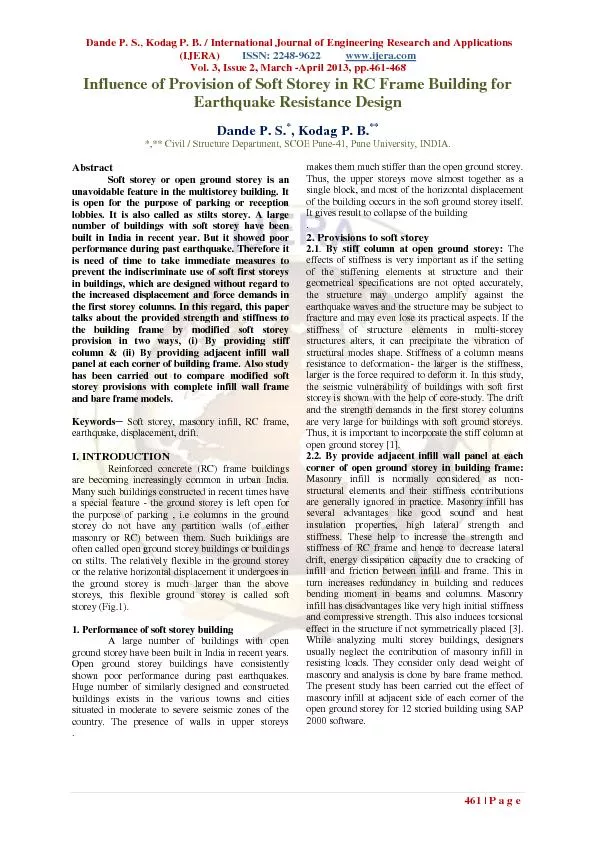
Dande P S Kodag P B IJERA ISSN 2248 9622 wwwijeracom Vol 3 Issue 2 March April 2013 pp 461 468 461 Page Influence of Provision of Soft Storey in RC Frame Building for Eart ID: 437519

Dande Kodag

Share:

Link:

Embed:

Download Presentation from below link

Download Pdf The PPT/PDF document "/ International Journal of Engineering R..." is the property of its rightful owner. Permission is granted to download and print the materials on this web site for personal, non-commercial use only, and to display it on your personal computer provided you do not modify the materials and that you retain all copyright notices contained in the materials. By downloading content from our website, you accept the terms of this agreement.


Presentation Transcript

Dande P. S. , Kodag P. B. / International Journal of Engineering Research and Applications (IJERA) ISSN: 2248 - 9622 www.ijera.com Vol. 3, Issue 2, March - April 2013, pp. 461 - 468 461 | Page Influence of Provision of Soft Storey in RC Frame Building for Earthquake Resistance Design Dande P. S. * , Kodag P. B. ** * ,** C ivil / S tructure Department, SC O E P une - 41, Pune University, INDIA. A bstra ct Soft storey or o pen ground storey is an unavoidable feature in the multistorey building. It is open for the purpose of parking or reception lobbies. It is also called as stilts storey. A large number of buildings with soft storey have been built in India in recent year. But it showed poor perfo rmance during past earthquake. Therefore it is need of time to take immediate measures to prevent the indiscriminate use of soft first storeys in buildings, which are designed without regard to the increased displacement and force demands in the first stor ey columns. In this regard, this paper talks about the provided strength and stiffness to the building frame by modified soft storey provision in two way s , (i) By provid ing stiff column & (ii) By provid ing adjacent infill wall panel at each corner of building frame. A lso stud y has been carried out to compare modified soft storey provisions with complete infill wall frame and bare frame models. Keywords ─ Soft storey, masonry infill, RC frame, earthquake, di splacement , drift . I. INTRODUCTION Reinforced concrete (RC) frame buildings are becoming increasingly common in urban India. Many such buildings constructed in recent times have a special feature - the ground storey is left open for the purpose of parking , i.e columns in the ground storey do not have any partition walls (of either masonry or RC) between them. Such buildings are often called open ground storey buildings or buildings on stilts. The relatively flexible in the ground storey or the relative horizontal displacement it undergoes in the ground storey is much larger than the above storeys, this flexible ground storey is called soft storey (Fig.1). 1 . Perf ormance of soft storey building A large number of build ings with open ground storey have been built in India in recent years. Open ground storey buildings have consistently shown poor performance during past earthquakes. Huge number of similarly designed and constructed buildings exists in the various towns an d cities situated in moderate to severe seismic zones of the country. The presence of walls in upper storeys makes them much stiffer than the open ground storey. Thus, the upper storeys move almost together as a single block, and most of the horizontal displacement of the building occurs in the soft ground storey itself. It gives result to collapse of the building . 2 . Provisions to soft storey 2.1 . By stiff column at open ground storey : The effects of stiffness is very important as if the setting of the stiffening elements at structure and their geometrical specifications are not opted accurately, the structure may undergo amplify against the earthquake waves and the structure may be subject to fracture and may even lose its practic al aspects. If the stiffness of structure elements in multi - storey structures alters, it can precipitate the vibration of structur al modes shape. Stiffness of a column means resistance to deformation - the larger is the stiffness, larger is the force requir ed to deform it. In this study, the seismic vulnerability of buildings with soft first storey is shown with the help of core - study . The drift and the strength demands in the first storey columns are very large for buildings with soft ground storeys. Thus, it is important to incorporate the stiff column at open ground storey [1] . 2.2. By provide adjacent infill wall panel at each corner of open ground storey in building frame : Masonry infill is normally considered as non - structural elements and their stiffness contributions are generally ignored in practice. Masonry infill has several advantages like good sound and heat insulation properties, high lateral strength and stiffness. These help to increase the strength and stiffness of RC frame and hence to decrease lateral drift, energy dissipation capacity due to cracking of infill and friction between infill and frame. This in turn increases redundancy in building and reduces bending moment in beams and columns. Masonry infill has disadvantages like very high initial stiffness and compressive strength. This also induces torsional effect in the structure if not symmetrically placed [3] . While analyzing multi storey buildings, designers usually neglect the contribution of masonry infill in resi sting loads. T hey consider only dead weight of masonry and analysis is done by bare frame method. The present study has been carried out the effect of masonry infill at adjacent side of each corner of the open ground storey for 12 storied building using SAP 2000 softwar e. . Dande P. S. , Kodag P. B. / International Journal of Engineering Research and Applications (IJERA) ISSN: 2248 - 9622 www.ijera.com Vol. 3, Issue 2, March - April 2013, pp. 461 - 468 462 | Page Fig1: Soft Storey or Open Ground Storey building [ 5 ] . 3 . Classification based on IS 1893 code : 3.1. Soft storey: It is one in which the lateral stiffness is less than 70 percent of that in the storey above or less than 80 percent of the average lateral stiffness of the three storey e s above. 3.2. Weak storey: It is one in which the storey lateral strength is less than 80 perc ent of that in the storey above. The storey lateral strength is the total strength of all seismic force resis ting elements sharing the storey shear in the considered direction. [5] The aim of the present analytical work is to study the performance of soft storey building by modified provision at open ground storey with hazardous features need to be recognized immediately and necessary measure taken to improve performance of building, to minimized the lateral deflection, to assess the economic structure. II. ANALYTICAL WORK A 12 - storey building with RC moment resisting frame with open first storey and unreinforced brick infill walls (panels) in upper storeys, chosen for this study. The building is deliberately kept symmetric in both orthogonal directions in plan to avoid torsional response under pure lateral forces. 1 . Types of cases used for analysis of structure There are three basic cases with sub - cases considered to analyze 12 - storey (G+11) structure so that proper provision of soft storey can be predicted. (I) General building models: (Fig.2) (I.1) Building with one full infill masonry wall (230mm) (External &internal wall) in all storey includ ing ground storey. (I.2) Building modeled as bare frame. However, masses of the walls as in model I.1 are included in the model. (II)Building model with soft storey: (Fig.3) (II.1) Building model with no masonry wall in first ground storey and full infill masonry wall (230mm) (Ext ernal &internal wall) in all above storey es . (II.2) Building model with no masonry wall in first three storey (G+2) and full infill masonry wall (230mm) (External &internal wall) in all above storey es . (II.3) Building model with no masonry wall in first six storey (G+5) and full infill masonry wall (230mm) (External &internal wall) in all above storey es . (III) Building models present with modified soft storey provision: (Fig.4) ( III.1 )Building model with no masonry wall in first ground storey and full infill masonry wall (230mm) (External &internal wall) in all above storey es , and provided with ground storey columns much stiffer as compared to above storey columns. ( III.2 )Building model with one full infill masonry wall at the adjacent s ide of each corner in first ground storey and one full infill masonry wall (230mm) (External &internal wall) in all above storey es . 2 . Structural Data Building consists of 15 m in short & 35 m in long direction, so from preliminary design the sizes of various structural members were estimated as follows Brick masonry wall Thickness: Brick masonry wall (modulus of elasticity E=13500000KN/m 2 [2] & P oi s son ‟ s ratio of masonry µ= 0.15) is provided with 230 mm thickness for all storey of different cases. And 1.5m height parapet wall is also considered. Storey height is kept as 4.1m for open ground floor and 3.1m for all upper floors. Grade Fe - 415 hot rolled deformed steel is used. Concre te having M - 20 (E=5000√f ck as per IS456) strength for columns, beams and slabs is to be employed. Columns were kept of 1 8 ”x1 8 ” ( 450 x 450 mm) size for overall structure and 2 7.5 ″x2 7.5 ″ ( 7 00 x 7 00 mm) size only for stiff column provision to avoid the local eccentricity. All beams are of uniform size of 12″ × 1 8 ″ (300 × 45 0mm) having 6″ (150 mm) thick slab for all the spans. 3 . Gravity loading (As per IS: 456 – 2000 & IS: 875 (Part II) - 1987) For Dead Load (DL), Intensity of wall =1 6 . 79 KN/ m (for4.1mheight) & =12. 19 KN / m (for 3.1m height), Intensity of parapet wall =6.9 KN / m (for 1.5m height) , Intensity of slab load=3.75 KN / m 2 , Intensity of floor finish load=1 KN / m 2 , Intensity of roof treatment load=1.5 KN / m 2 and Intensity of live load (LL) =3 KN / m 2 . 4 . Lateral loading ( as per IS1893 - 2002) Lateral loading consists of earthquake loading. Earthquake loading has been calculated by the program and it has been applied to the mass center of the building. Since the building under consideration was in Zone – III with standard occupancy so the result was computed as follows: Case: 1.2(DL+LL+EQX) and 1.2(DL+LL+EQY) Period Calculation: Program & by Code Calculated Bottom Storey: Open ground storey or Base Response reduction factor, R = 5 Dande P. S. , Kodag P. B. / International Journal of Engineering Research and Applications (IJERA) ISSN: 2248 - 9622 www.ijera.com Vol. 3, Issue 2, March - April 2013, pp. 461 - 468 463 | Page Importance factor, I = 1 Building Height H = 38.2 m Soil Type = II (Medium Soil) Seismic zone factor, Z = 0.16 5 . Figure showing considered building models (I.1) (I.2) Fig 2 : General building models – (I.1) Complete infill masonry & (I.2) Bare frame. (II.1) Fig 3 : Building models present with soft storey - (II.1) G round storey as a Soft storey, (III.1) (III.2) Fig4: Building models present with modified soft storey provision - (III.1) Stiff column at Open Ground Storey (i.e. Soft storey), (III.2) One full infill masonry wall at the adjacent side of each corner in Open Ground S torey. Dande P. S. , Kodag P. B. / International Journal of Engineering Research and Applications (IJERA) ISSN: 2248 - 9622 www.ijera.com Vol. 3, Issue 2, March - April 2013, pp. 461 - 468 464 | Page 6 . Analysis of the building Response spectrum analysis is performed for the seven models of the building using SAP2000. The frame members are modeled with rigid end zone, the walls are modeled as panel element and floor are modeled as diaphragms rigid in plane. The lateral loads generated by SAP correspond to the seismic zone III and the 5% damping response spectrum given in IS 1893 - 1984. The natural period values are calculated by SAP, by solving the eigen value problem of the model . Thus the total earthquake load generated and its distribution along the height corresponding to the mass and stiffness distribution as modeled by SAP. III. RESULTS AND DISSCUSSIONS The maximum displacement, maximum bending moment & shear force and fundamental natural period results for the 12 - storey structure are obtained on the of three different cases i.e. (I) General building models I.1 & I.2, (II) Building models present with soft storey II.1, II.2 & II.3 and (III) Building models present with m odified soft storey provision III.1 & III.2 for 1.2(DL+LL+EQX) (earthquake force from X - direction) & 1.2(DL+LL+EQY) (earthquake force from Y - direction). Fig 5: Plan of structure . 1. Maximum Lateral Displacement: Table 1 : (I) General building models Comparison of max. disp. of Models I.1 & I.2 in X - dir . Joint No. Storey Height(m) Model (I.1) (mm) Model (I.2) (mm) 1 0 0 0 2 4.1 0.0718 12.7 3 7.2 0.135 23.9 4 10.3 0.204 34.5 5 13.4 0.276 44.3 6 16.5 0.350 53.2 7 19.6 0.424 61.4 8 22.7 0.497 68.6 9 25.8 0.567 74.8 10 28.9 0.633 80 11 32 0.695 84 12 35.1 0.750 86.8 13 38.2 0.799 88.2 Table 2: (I) General building models Comparison of max. disp. of Models I.1 & I.2 in Y - dir . Joint No. Storey Height(m) Model (I.1) (mm) Model (I.2) (mm) 1 0 0 0 2 4.1 0.0903 7.07 3 7.2 0.183 12.7 4 10.3 0.292 18 5 13.4 0.414 22.9 6 16.5 0.545 27.6 7 19.6 0.683 31.8 8 22.7 0.826 35.7 9 25.8 0.696 39.1 10 28.9 1.11 42.1 11 32 1.25 44.5 12 35.1 1.38 46.3 13 38.2 1.51 47.5 Table 3: (II)Building models present with soft storey Comparison of max. disp. of Models II.1, II.2 & II.3 in X - dir. Joint No. Storey Height (m) Model (II.1) (mm) Model (II.2) (mm) Model (II.3) (mm) 1 0 0 0 0 2 4.1 9.10 11.9 10.1 3 7.2 9.21 22.3 19.2 4 10.3 9.29 30 27.9 5 13.4 9.38 30.2 36.3 6 16.5 9.47 30.3 44 7 19.6 9.56 30.4 49.7 8 22.7 9.64 30.6 49.9 9 25.8 9.72 30.7 50 10 28.9 9.79 30.8 50.2 11 32 9.86 30.9 50.3 12 35.1 9.93 31 50.4 13 38.2 9.99 31.1 50.6 Dande P. S. , Kodag P. B. / International Journal of Engineering Research and Applications (IJERA) ISSN: 2248 - 9622 www.ijera.com Vol. 3, Issue 2, March - April 2013, pp. 461 - 468 465 | Page Table 6 : (III) Building models present with modified soft storey provision Comparison of maximum displacement of Models III.1 & III.2 in Y - direction Joint No. Storey Height(m) Model (III.1) (mm) Model (III.2) (mm) 1 0 0 0 2 4.1 1.54 0.732 3 7.2 1.67 0.880 4 10.3 1.79 1.04 5 13.4 1.93 1.21 6 16.5 2.07 1.39 7 19.6 2.21 1.58 8 22.7 2.36 1.77 9 25.8 2.50 1.95 10 28.9 2.64 2.14 11 32 2.78 2.32 12 35.1 2.92 2.50 13 38.2 3.04 2.67 Table 7 : Comparison of I.1,II.1,III.1 & III.2 Maximum displacement in X - direction Joint No. Storey Height (m) Model (I.1) (mm) Model (II.1) (mm) Model (III.1) (mm) Model (III.2) (mm) 1 0 0 0 0 0 2 4.1 0.0718 9.10 2.60 0.689 3 7.2 0.135 9.21 2.68 0.767 4 10.3 0.204 9.29 2.74 0.846 5 13.4 0.276 9.38 2.81 0.926 6 16.5 0.350 9.47 2.88 1.01 7 19.6 0.424 9.56 2.94 1.08 8 22.7 0.497 9.64 3.00 1.16 9 25.8 0.567 9.72 3.06 1.23 10 28.9 0.633 9.79 3.11 1.30 11 32 0.695 9.86 3.16 1.37 12 35.1 0.750 9.93 3.21 1.43 13 38.2 0.799 9.99 3.25 1.49 Table 8 : Comparison of I.1,II.1,III.1 & III.2 Maximum displacement in Y - direction Joint No. Storey Height (m) Model (I.1) (mm) Model (II.1) (mm) Model (III.1) (mm) Model (III.2) (mm) 1 0 0 0 0 0 2 4.1 0.0903 5.59 1.54 0.732 3 7.2 0.183 5.79 1.67 0.880 4 10.3 0.292 5.98 1.79 1.04 5 13.4 0.414 6.18 1.93 1.21 6 16.5 0.545 6.39 2.07 1.39 7 19.6 0.683 6.60 2.21 1.58 8 22.7 0.826 6.81 2.36 1.77 9 25.8 0.696 7.02 2.50 1.95 10 28.9 1.11 7.23 2.64 2.14 11 32 1.25 7.44 2.78 2.32 12 35.1 1.38 7.64 2.92 2.50 13 38.2 1.51 7.83 3.04 2.67 Table 4: (II)Building models present with soft storey Comparison of max. disp. of Models II.1, II.2 & II.3 in Y - dir. Joint No. Storey Height (m) Model (II.1) (mm) Model (II.2) (mm) Model (II.3) (mm) 1 0 0 0 0 2 4.1 5.59 6.66 5.63 3 7.2 5.79 12 10.2 4 10.3 5.98 16.2 14.6 5 13.4 6.18 16.5 18.9 6 16.5 6.39 16.8 23 7 19.6 6.60 17.2 26.2 8 22.7 6.81 17.5 26.6 9 25.8 7.02 17.8 27.1 10 28.9 7.23 18.2 27.5 11 32 7.44 18.5 27.9 12 35.1 7.64 18.8 28.3 13 38.2 7.83 19.1 28.7 Table 5: (III) Building models present with modified soft storey provision Comparison of max. disp. of Models III.1 & III.2 in X - direction Join t No. Storey Height(m) Model (III.1) (mm) Model (III.2) (mm) 1 0 0 0 2 4.1 2.60 0.689 3 7.2 2.68 0.767 4 10.3 2.74 0.846 5 13.4 2.81 0.926 6 16.5 2.88 1.01 7 19.6 2.94 1.08 8 22.7 3.00 1.16 9 25.8 3.06 1.23 10 28.9 3.11 1.30 11 32 3.16 1.37 12 35.1 3.21 1.43 13 38.2 3.25 1.49 Dande P. S. , Kodag P. B. / International Journal of Engineering Research and Applications (IJERA) ISSN: 2248 - 9622 www.ijera.com Vol. 3, Issue 2, March - April 2013, pp. 461 - 468 466 | Page Fig 6: Comparison of max . disp . for General building models I.1 & I.2 in X - dir. with respect to height. (Table 1) Fig 7 : Comparison of max. disp. for General building models I.1 & I.2 in Y - dir. with respect to height. (Table 2 ) Fig 8 : Comparison of max . disp . of Building models present with Soft storey II.1, II.2 & II.3 in X - dir. (Table3) Fig 9: Comparison of max. disp. of Building models present with Soft storey II.1, II.2 & II.3 in Y - dir. (Table4) Fig 10: Comparison of Max . disp . of Building models present with modified soft storey provision III.1 & III.2 in X - dir.(Table5 ) Fig 1 1 : Comparison of Max. disp. of Building models present with modified soft storey provision III.1 & III.2in Y - dir.(Table 6 ) Fig 1 2 : Comparison of Max . disp . of Building models I.1, II.1, III.1 & III.2 in X - dir. with respect to height. Fig 1 3 : Comparison of Max. disp. of Building models I.1, II.1, III.1 & III.2 in Y - dir. with respect to height. 0 5 10 15 20 25 30 35 40 45 0 20 40 60 80 100 Storey Height (m) Maximum Displacement (mm) I.1 I.2 0 5 10 15 20 25 30 35 40 45 0 10 20 30 40 50 Storey Height (m) Maximum Displacement (mm) I.1 I.2 0 5 10 15 20 25 30 35 40 45 0 10 20 30 40 50 60 Storey Height (m) Maximum Displacement (mm) II.1 II.2 II.3 0 5 10 15 20 25 30 35 40 45 0 5 10 15 20 25 30 35 Storey Height (m) Maximum Displacement (mm) II.1 II.2 II.3 0 5 10 15 20 25 30 35 40 45 0 0.5 1 1.5 2 2.5 3 3.5 Storey Height (m) Maximum Displacement (mm) III.1 III.2 0 5 10 15 20 25 30 35 40 45 0 0.5 1 1.5 2 2.5 3 3.5 Storey Height (m) Maximum Displacement (mm) III.1 III.2 0 5 10 15 20 25 30 35 40 45 0 2 4 6 8 10 12 Storey Height (m) Maximum Displacement (mm) I.1 II.1 III.1 III.2 0 5 10 15 20 25 30 35 40 45 0 2 4 6 8 10 Storey Height (m) Maximum Displacement (mm) I.1 II.1 III.1 III.2 Dande P. S. , Kodag P. B. / International Journal of Engineering Research and Applications (IJERA) ISSN: 2248 - 9622 www.ijera.com Vol. 3, Issue 2, March - April 2013, pp. 461 - 468 467 | Page Table 1/2 and Fig. no. 6 /7 shows comparison of the lateral displacement profile of complete infill wall (panel) model I.1 & bare frame model I.2 in both X - dir. and Y - dir. respectively. It indicates the effect of displacement variations of adopted modeling between them. Table 3/4 and Fig. no. 8/9 show s the comparison of the lateral displacement profile of building model present with soft storey Models II.1, II.2& II.3 in both X - dir. and Y - dir. respectively. It indicates the abrupt change in drift at storey level by soft storey. Table 5/6 and Fig. no. 10/11 show the comparison of the lateral displacement profile of building model present with modified soft storey provision Models III.1 & III.2 in both X - dir. and Y - dir. respectively. It indicates to control the sudden change in drift at first storey level by modified soft storey provision. From the above tables & figures , the abrup t change in the slope of the profile indicates the stiffness irregularity. All the displacement profiles corresponding to model having stiffness irregularity (i.e. Models II.1, II.2 II.3) have sudden change of slope at next floor level. However the other m odels (i.e. Models I.1, I.2, III.1 & III.2) shows smooth displacement profiles. The interstorey drift is largest in the first storey for the model with soft storey (i.e. Model II.1). This implies that the ductility demand on the columns in the first storey for this model is the largest [ 4 ]. For the models I.1, III.1 & III.2 which do not have stiffness irregularity and the first floor displacement is small. 2. Maximum Bending Moment (BM) and Shear Force (SF): Table 9: Maximum BM and SF in X - direction. Max Moment(KNm) Max Shear(KN) Model First Column Second Column First Column Second Column I.1 0.497 0.892 0.957 1.416 I.2 153.641 163.487 97.104 99.764 II.1 177.617 24.996 94.709 31.521 III.1 127.980 17.547 94.982 22.928 III.2 13.969 2.991 6.411 0.442 Table 10: Maximum BM and SF in Y - direction. Max Moment(KNm) Max Shear(KN) Model First Column Second Column First Column Second Column I.1 0.571 0.445 0.755 0.875 I.2 110.848 112.840 61.23 61.496 II.1 115.973 13.036 60.097 14.030 III.1 90.488 9.874 60.677 11.203 III.2 18.227 5.861 5.767 3.229 From Table no. 9 & 10 shows maximum bending and shear force in the columns in the ground and first floor. In case of soft storey building the BM and SF (strength) demands are severely higher for first storey columns. The introduction of walls panels in the first storey (i.e. Model I.1 & III.2) reduces the forces in the first storey columns. As the forces is distributed in proportion to the stiffness of the member, the force in the columns of the upper storey for models I.1, II.1, III.1 & III.2 except bare frame model I.2 are significantly reduced due to presence of brick walls. The use of brick infill wall (panels) in complete infill model (i.e. Model I.1) and adjacent infill wall provided at each corner of th e ground floor building model (i.e. Model III.2) are reduced the BM and SF at first storey column compared to the other models. Interestingly, the drift demand on the first storey columns in case of Model I.1, Model III.1 and Model III.2 are very close as showing in lateral displacement result. But in this section, in case of models having stiff column at first storey level (i.e. Model III.1), BM and SF on first storey columns is very large as compared to complete infill model (i.e. Model I.1) and adjacent infill wall provided at each corner of the ground floor building model (i.e. Model III.2). 3. Natural Periods: Table 11: Fundamental Natural Periods F u ndamental Natural Period (sec) Models X - direction Y - direction Code Analysis Code Analysis I.1 0.58 0.3556 0.89 0.3556 I.2 0.58 2.3937 0.89 2.3937 II.1 0.58 1.0263 0.89 1.0263 III.1 0.58 0.6010 0.89 0.6010 III.2 0.58 0.5165 0.89 0.5165 Above Table no.11 shows the codal (IS 1893 - 2002) and analytical (by using SAP2000 software) natural periods of building models I.1, I.2, II.1, III.1 & III.2. It is seen that the analytical natural periods do not tally with the natural periods obtained by empirical expression of the code. Introduction of infill panels in the RC frame reduces the time period of bare frames and also enhances the stiffness of the structure. The bare frame idealization in model I.2 lead to severe overestimation of the natural period compared to the open first storey building model II.1. IV. CONCLUSION The object of this investigation is to study the effect of horizontal loading on reinforced concrete frame with brick masonry infill wall (panel) for different conditions including soft storey models. Deflections are one of the most important parameter to be considered in the design and anal ysis of tall building. Therefore deflection and other important parameters for lateral loads have been studied. The following conclusions can be drawn. (i)The displacement and force demands (i.e. BM & SF) in the first storey columns are very large for building with soft ground storey. It is difficult to provide such capacities in the columns of the first Dande P. S. , Kodag P. B. / International Journal of Engineering Research and Applications (IJERA) ISSN: 2248 - 9622 www.ijera.com Vol. 3, Issue 2, March - April 2013, pp. 461 - 468 468 | Page storey. When incorporated the infill wall (panel) at soft ground storey, these demand are significa ntly re duced . (ii)From the fundamental time period, it has been found that when there is no infill wall (panel) i.e. for bare frame model , the time period value is more than the value predicted by code. This indicates that modeling of RC frame building w ithout infill wall (panel) or bare frame model may not be appropriate for the analysis. When infill wall (panel) is incorporated, then shorten the time periods of other than bare frame models. (iii) When the bare frame model is subjected to lateral load, m ass of each floor acts independently resulting each floor to drift with respect to adjacent floors. Thus the building frame behaves in the flexible manner causing distribution of horizontal shear across floors. In presence of infill wall (panel), the relat ive drift between adjacent floors is restricted causing mass of the upper floors to act together as a single mass. In such case, the total inertia of the all upper floors causes a significant increase in horizontal shear force at base or in the ground floo r columns. Similarly increases the bending moment in the ground floor columns. (iv)T he presence of walls in upper storeys makes them much stiffer than open ground storey. Hence the upper storey move almost together as a single block and most of the horizo ntal displacement of the building occurs in the soft ground storey itself. Such building swing back and forth like inverted pendulums during earthquake shaking and columns in the open ground storey are severely stressed. It is clear that building with sof t storey will exhibit poor performance during a strong shaking. But the open first storey is an important functional requirement of almost all the urban multistory buildings and hence cannot be eliminated. Alternative measures need to be adopted for this s pecific situation. The under - lying principle of any solution to this problem is in (a) increasing the stiffness of the first storey; (b) provide adequate lateral strength in the first storey. The possible schemes to achieve the above are (III.1) stiff colu mn provided at open ground storey model and (III.2) adjacent infill wall provided at each corner of soft storey building model. The configuration of infill in the parking frame changes the behavior of the frame therefore it is essential for the structural system selected to be thoroughly investigated and well understood for catering to soft ground floor. The former is effective only in reducing lateral displacement on the first soft storey columns. ACKNOLEDGEMENT Author of this article would like to thank Principal, HOD and all the staff of Sinhgad college of Engineering & Technology, Vadgaon (Bk) , Pune and Pune University for support and opportunity. REFERANCES Journal Papers: [1] J . N. Arlekar, S . K. Jain and C.V.R. Murty , “ Seismic Response of RC Frame Buildings with Soft First Storeys,” Dept . of Civil Engineering, I.I.T., Kanpur, India. ( CBRI ) 1997. [2] Sujatha A., Jiji Anna Varughese, Bindhu K.R, “The Influence of Masonry Infill in RC Multi - Storey Buildings,” ( NCTT09) 6 - 7 Nov 2009 . [3] S . Haque, Khan M . A . , “Seismic Vulnerability of Columns of RC Framed Buildings with Soft Ground Floor,” International Journal Of Mathematical Models And Methods In Applied Sciences, Issue3,Volume2, 2008. [ 4 ] M.R. Amin, P. Hasan, B.K.M.A. Islam, “Effect of so ft storey on multistoried reinforced concrete building frame,” Bangladesh, ISBN: 978 - 984 - 33 - 4363 - 5, 4th Annual Paper Meet and 1st Civil Engineering Congress, December 22 - 24 , 2011 . [ 5 ] C V R Murty, the Classroom section, a series of short articles, 'Earthquake Tips ', related to earthquakes design & construction of buildings. I IT Kanpur and BMTPC , New Delhi. August 2004. [ 6 ] A.K . Chopra , D.P. Clough, R.W. Clough, “Earthquake Resistance of Building with a „SOFT‟ First Storey”, Earthquake Engineering and Structural Dynamics, Vol.1, 347 - 355, 1973 . [ 7 ] Bento R., Azevedo J., “ Behaviour coefficient assessment for Soft Storey Structures”, 12WCEE ,2000. Books: [ 8 ] P.Agrawal, M. Shrikhande Earthquake resistant design of structure (PHI Learning Pvt.Ltd. New Delhi, 2009). [ 9 ] Mario Paz & William Leigh, Structural Dynamics (Springer Pvt. Ltd. New Delhi, 2007).