/
JLEIC  SC Magnets:  Replace SF and JLEIC  SC Magnets:  Replace SF and

JLEIC SC Magnets: Replace SF and - PowerPoint Presentation

lindy-dunigan
lindy-dunigan . @lindy-dunigan
Follow
342 views
Uploaded On 2019-11-19

JLEIC SC Magnets: Replace SF and - PPT Presentation

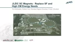
JLEIC SC Magnets Replace SF and High CM Energy Needs Tim Michalski Ruben Fair Renuka RajputGhoshal Probir Ghoshal Superferric Magnets in JLEIC To date JLEIC has had Superferric SF Dipoles and Quadrupoles as the BASELINE technology for both the Booster Ring and Ion Collider Ring ID: 765595

energy dipole magnets gev dipole energy gev magnets ring design coil collider ion magnet radius ramp curved baseline bend

Share:

Link:

Embed:

Download Presentation from below link

Download Presentation The PPT/PDF document "JLEIC SC Magnets: Replace SF and" is the property of its rightful owner. Permission is granted to download and print the materials on this web site for personal, non-commercial use only, and to display it on your personal computer provided you do not modify the materials and that you retain all copyright notices contained in the materials. By downloading content from our website, you accept the terms of this agreement.


Presentation Transcript

JLEIC SC Magnets: Replace SF and High CM Energy Needs Tim Michalski, Ruben Fair, Renuka Rajput-Ghoshal, Probir Ghoshal

Superferric Magnets in JLEICTo date, JLEIC has had Superferric (SF) Dipoles and Quadrupoles as the BASELINE technology for both the Booster Ring and Ion Collider Ring The SF Model Dipole Prototype and Test project did not get funded under the most recent FOA R&D Funding round Should JLEIC continue with an unvalidated technology as part of its baseline? Short answer is NONeed to define an alternative baseline SC magnet solution for all current applications of SF magnets in JLEICThe main focus has been on the Dipoles in the Booster and Ion Collider RingBooster: 3T, 1.42m Long, 10 cm x 6 cm Beam Pipe Aperture, Straight Magnets, 8.245° Bend Angle, 9.89m Bend Radius, 2.56 cm Sagitta, 1 T/s Ramp RateIon Collider Ring: 3T, 2 each x 4m Long, 10 cm x 6 cm Beam Pipe Aperture, Straight Magnets, 4.2° Bend Angle, 109m Bend Radius, 1.83 cm Sagitta per 4m, .05 T/s Ramp Rate 2

Booster SC Dipole Alternatives (New Baseline?) Booster: 3.45 T , 1.42m Long, 10 cm x 6 cm Beam Pipe Aperture, Straight Magnets, 8.245° Bend Angle, 9.89m Bend Radius, 2.56 cm Sagitta, 1 T/s Ramp RateConversion to a cosine-theta magnet design will create a round coil aperture – need a revised beam pipe aperture valueConsider 15% increase in field strength for High CM Energy design – from 3 T to 3.45 T (9.2 GeV max energy)Additional High Energy Booster limits – 10.5 GeV requires 3.94 T dipoles, 13 GeV requires 4.88 T)SIS300 (INFN and IHEP versions) as reference designsTested prototypes to 4.5 T and 6 T, respectivelyRequires modified Rutherford cable for fast ramping to 1 T/sINFN’s version of SIS300 magnet is curvedIHEP performed a study of curved vs straight dipoles based on their UNK dipole design (2 layer coil)GSI 001 Magnet Design - A body of work adapting a RHIC dipole towards SIS200/SIS300 performance Focus on new conductor design – low loss for fast ramping Other design/material changes to reduce losses 3

SIS300 INFN Magnet Design 4 P. Fabbricatore , et al, “The construction of the model of the curved fast ramped superconducting dipole for FAIR SIS300 synchrotron”, ASC 2010

SIS300 IHEP Magnet Design 5 SIS 300, a fast-ramping heavy ion synchrotron with a rigidity of 300 T-m, with 6 T, 100 mm coil aperture 2.6 m long superconducting dipoles, ramped at 1 T/s. The fast ramp rate requires a magnet design that minimizes AC losses and field distortions during ramping. A two layer cos-theta magnet design, using a cored Rutherford cable, has been chosen.

GSI 001 (BNL) Magnet Design SIS200 1 m long model dipole GSI 001 Goal of 4T at 1 T/s ramp rate Based on the RHIC dipole design but incorporating a number of loss reduction features6

Rutherford Cable Design for High Ramp Rate 7 Required Changes from “Standard” Rutherford Cable Reduced Filament Size Reduced Filament Twist Pitch CuMn Interfilamentary Matrix vs Cu Stay Bright ® Strand Coating Thin layer of SS between cable layers

Curved vs Straight Dipole – Performance Testing Historically, there are two techniques for building bent (curved) magnets, depending on the required radius of curvature of the magnet.Magnets with relatively large radius of curvature (RHIC). Collared coil, iron yoke and helium vessel half-shells (denoted as the cold mass, when assembled) are produced straight and after assembly the cold mass is bent with a special tool and then the helium vessel half-shells are welded. In this case a little curvature of the coil does not cause sufficient strains in the superconducting material (NbTi), to result in magnet degradation. Magnets with relatively small radius of curvature (INFN). The coil , iron yoke, collar sections, and helium half-shells are produced curved. This technique is essentially more complicated and more expensive in comparison with the first way. To define a suitable bending technique, a 1 m long dipole, manufactured in the framework of the UNK project, was chosen. The straight dipole was tested, then bent with 50 m radius of curvature, and retested . The dipole was bent by clamps in a special frame which supplied the bending of the dipole during test . A 1 m long dipole bent at a 50 m radius requires a deflection in the center of 3 mm. Straight and bent dipoles were tested without iron yoke and had practically equal AC loss values, which were higher by a factor of 1.3 than the losses in the dipole with iron yoke. 8

9 Curved vs Straight Dipole – Performance Testing CONCLUSIONS The main results of dipole test before and after magnet bending are the following: 1) Bending of the collared dipole coil (50 m curvature radius) did not produce turn-to-turn shorts and did not decrease ground insulation resistance. 2) The dipole begun to train afresh after the bending. Characteristics of training and ramp rate dependence of the straight and bent dipoles are similar. 3) The critical current of the dipole did not decrease after the bending which caused about 40 MPa stress in turns of the dipole . 4) 1000 cycles (0–5 T–0 with 0.75 T/s magnetic field ramp rate ) practically did not influence the critical current value and ramp rate dependence in the bent dipole. 5) Cable losses had increased after a storage period of twelve years as the coil turns were under high pressure at room temperature without motion. 6) AC losses were practically unchanged, after dipole bending . 7) Harmonic was increased by dipole bending. This value should be taken into account during development of correction systems .

Ion Collider Ring – New BaselineCurrent Baseline: Ion Collider Ring: 3T, 2 x 4 m Long, 10 cm x 6 cm Beam Pipe Aperture, Straight Magnets, 4.2° Bend Angle, 109 m Bend Radius, 1.83 cm Sagitta per 4 m, .05 T/s Ramp RateNew Baseline:3T8m Long – single magnetCosine-Theta design – single layer coilCurvedNeed to define/address Beam Pipe Aperture – drives Coil Aperture109 m Bend Radius.05 T/s Ramp RateNew Baseline requirements are essentially validated by the RHIC Dipole designIon Collider Ring requires smaller bend radius (less than half of RHIC)Need to assess Beam Pipe Aperture with respect to Dynamic Aperture  Drives Coil Aperture 10

JLEIC Standard Energy Upgrade Path JLEIC CM energy range is largely determined by the proton energy which is determined by the maximum field strength of the ion collider ring dipoles 3 T for the present baseline, super-ferric magnet is adopted for cost efficiency, sufficient for covering a sweet spot of EIC physicsFor a future energy upgrade, new magnets of 6 T (super-ferric or cosine-theta), 8.4 T (LHC) and 12 T (HI-LHC R&D demonstrated) may be considered.In principle, the electron collider ring energy may also be increased up to ~14 GeV (limited by synchrotron radiation), either requiring upgrade of CEBAF or ramping energy up in the ringJLEIC energy upgrade can reach ultimately ~150 GeV (by 14 GeV e x 400 GeV p), following the same footprint of the present JLEIC baselinePresent JLEIC standard approach to meet EIC science Present baseline: 20 GeV to ~69 GeV CM energy  30 to 100 GeV proton energy, up to 40 GeV/u heavy ion energy 3 to 12 GeV electron energy Energy upgrade: up to 98 GeV CM energy  up to 200 GeV proton energy, up to 80 GeV/u heavy ion energy 3 to 12 GeV electron energy This standard approach will be documented in the pCDR 11 Standard Upgrade Path ( Most straightforward ) Doubling dipole field Doubling proton energy No touch on the electron ring

JLEIC Ion Complex Layout for Standard Upgrade 12 ion sources ion linac booster (0.285 to 8 GeV) collider (8 to 100 GeV ) DC/ERL cooler DC cooler Present baseline Single Booster Ring Collider Ring Injection (GeV) Extraction (GeV) Dipole range Injection (GeV) Collision (GeV) Dipole range DC cooling (MeV) Baseline 0.285 8 11.2 8 100 11.5 4.3 Upgrade 0.285 9.2 12.9 9.2 200 20 5.0 Design considerations: SC dipole field range should not exceed a factor of 20 Prefer single booster ring (re-introducing the 2 nd booster ring  slow, complication, extra cost) Within the DC cooling range (electron energy < 8 MeV, better < 6 MeV) Technology Assumptions for the Baseline: Booster is an 8 GeV injector to the Ion Collider Ring Ion Collider Ring uses 3T Superferric Dipoles (and associated quadrupoles) Ion Collider Ramp rate (injection to max energy in 1 minute) = ~.05 T/sec Bunch Control RF Cavities, Accelerating SRF Cavities, and Crab Cavities – quantities are baselined here IR FFQs are at reasonably high coil fields, requiring Nb 3 Sn conductor

High CM Energy Solution – What Changes? Assumptions for the High (100 GeV) CM Energy Ion Complex: Booster increase to 9.2 GeV injection to the Ion Collider RingArc dipole magnets from 3T to 6T – drop in replacement as an upgradeDouble the strength of all other magnets in the arcs and straightsIR layout change due to limits on FFQs  Double the amp-turns, double the DC Power Ion Collider Ring ramp rate stays the same = ~.05 T/sec Double the Ion Collider Ring Crab Cavities and associated RF Power Double the Bunch Control Cavities and associated RF Power Impact to ERL Cooler (see Zhang presentation) LCW increase for additional DC Power and RF Power Service building space for DC Power and RF Power Increase in AC Power Utility 13

Arc Dipole Magnets from 3T to 6T  Due to the level of attention and scrutiny associated with this topic, JLEIC must present a 6T dipole solution which is a low technical risk and within the State-of-the-Art !Drop in replacement, at the cryostat levelArc half-cell length is 11.4m, single cryostatCryostat accommodates 8m dipole, .8m quadrupole, sextupoleChange from SF Technology with CICC to Cos with Rutherford Cable (Low Loss)Impact to DC Powering:SF dipoles are 13.5kA, low voltage (~75V per arc string)Anticipate Cos to be lower current (8kA max as target), higher voltage Higher inductance due to higher stored energy and lower operating currentLower operating current – higher coil packing factor in order to achieve the required field and field quality with good magnetic/conductor efficiency Power supplies not compatible for two different magnet technologies Cryogenic loads need to be evaluated Static heat load should be equivalent 14

Accelerator Dipole Comparison Chart 15 Parameter Units JLEIC 100 GeV Ions (Baseline) JLEIC 200 GeV Ions (High Energy) RHIC SIS300 INFN Version SIS300 IHEP Version Technology Superferric Cos-Theta Cos-Theta Cos-Theta Cos-Theta Field Strength T 3.06 6.12 3.5 4.5 6 Operating Current kA 13.5 8 (assumed max) 5.5 8.9 6 Aperture mm dia or mm x mm 100 x 60 Beam tube 60- beam tube 80 - coil 69 - beam tube 80 - coil 86 – beam tube 100 - coil 80 – beam tube 100 - coil Layers of Conductor (Cos-Theta) n/a 2 1 1 2 Magnetic Length m 2 - 4m 8m total 8 9.45 7.757 2.6 Sagitta (or center curve offset) cm 1.83 Per 4m segment 7.3 4.85 11.3 1.7 Beampipe Straight/Curved Straight 2 - 4m Dipoles 2 deg camber Curved Curved Curved Curved (demonstrated by UNK dipole) Conductor TAMU CICC Low Loss Rutherford Rutherford Low Loss Rutherford Low Loss Rutherford Bending Radius m 109 109 243 66.7 50 Bending Angle deg 4.2 4.2 2.23 6.67 2.98 Ramp Rate T/s 0.05 0.05 0.06/.042 1 1 LHe Cooling Flow inside CICC Forced Flow Diffusion Cooling Forced Flow Diffusion Cooling Forced Flow Forced Flow Operating TempK4.54.54.64.54.5

RHIC Dipole Magnets – Consider Direct Use RHIC Magnets – 3.45 T, 9.45 m Magnetic Length, 243 m Bend RadiusFrom: “The RHIC Magnet System for NIM”, BNL Topic No. 610-20 (AM-MD-311)Performance at average quench current is 4.52 TAssume performance at min quench current less 10% - Max Field = 3.90 T16

SummaryBooster Dipole Magnets: There is a solution in cosine-theta m agnetsLook at energy design requirements of High CM EnergyRamp rate of 1 T/s is achievable – requires low loss Rutherford cablePreliminary validation by SIS300/GSI 001 magnet designsPrototype program still requiredNeed to get more information than what is presented in technical papersIon Collider Ring Dipole Magnets:New Baseline in cosine-theta magnets is low technical riskRHIC magnet design validates most parameters Ion Collider Ring, High CM Energy Dipole Magnets:There is a solution in cosine-theta magnets 6 T, Curved, 2 layer coil design has been prototyped and tested (IHEP)Prototype program requiredNeed to get more information than what is presented in technical papersAlternative – look at lower operating temperature as a means to get a 1 layer coil design (less technical risk for curved magnet, requires higher operating cost for cryogenics) Alternative – look at Nb3Sn to get a 1 layer coil design (higher cost magnets, brittle coil structure, can it be build curved, 4.5 K operation) Direct Use of RHIC Dipole Magnets: Length and bend radius would require adaptation of JLEIC collider ring layout Bend radius is more than 2X 17