/
Professor, College of civil Engineering, Tongji University, Shanghai 2 Professor, College of civil Engineering, Tongji University, Shanghai 2

Professor, College of civil Engineering, Tongji University, Shanghai 2 - PDF document

lindy-dunigan
lindy-dunigan . @lindy-dunigan
Follow
427 views
Uploaded On 2015-11-01

Professor, College of civil Engineering, Tongji University, Shanghai 2 - PPT Presentation

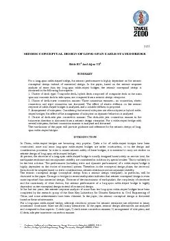
2123CHOICE OF DECK TYPEAt the conceptual design stage of a longspan cablestayed bridge there are four deck types can be consideredconcrete deck composite deck steel deck and hybrid deck steel o ID: 179481

2123CHOICE DECK TYPEAt the

Share:

Link:

Embed:

Download Presentation from below link

Download Pdf The PPT/PDF document "Professor, College of civil Engineering,..." is the property of its rightful owner. Permission is granted to download and print the materials on this web site for personal, non-commercial use only, and to display it on your personal computer provided you do not modify the materials and that you retain all copyright notices contained in the materials. By downloading content from our website, you accept the terms of this agreement.


Presentation Transcript

Professor, College of civil Engineering, Tongji University, Shanghai 200092, P.R.C.Doctor, College of civil Engineering, Tongji University, Shanghai 200092, P.R.C.SEISMIC CONCEPTUAL DESIGN OF LONG-SPAN CABLE-STAYED BRIDGEShide HU And Aijun YESUMMARY 2123CHOICE OF DECK TYPEAt the conceptual design stage of a long-span cable-stayed bridge, there are four deck types can be considered:concrete deck, composite deck, steel deck and hybrid deck (steel or composite deck in main span and concretedeck in side spans). The cable-stayed bridge with hybrid deck (hybrid cable-stayed bridge), in particular, isattracting more interests with its superior static performance and construction speed. Many hybrid cable-stayedbridges have been constructed or under construction. So, it is essential to compare the dynamic behavior ofhybrid cable-stayed bridge with other cable-stayed bridges. In the chapter, Xupu Bridge in Shanghai is taken asan example to carry out the study.Xupu Bridge is a hybrid cable-stayed bridge with two A shaped towers, its spans are40m+339m+45m+590m+45m+339m+240m. The deck system is composed of composite deck in mainspan and prestressed concrete deck in side spans. The spherical hinged movable bearings are erected on theanchor piers, and the pot rubber bearings are erected on the other side piers. Besides, there are limiters erectedbetween the deck and side piers in the transverse direction. The spacing between deck and anchor pier is 200mm,the spacing between deck and the other side piers is 10~20mm. Another alternative of Xupu Bridge is acomposite cable-stayed bridge with span of 96m+142m+590m+142m+96m. Apart from the deck type, the otherdesign is as same as the existing Xupu Bridge.In order to analyze and compare the dynamic behavior of the two alternatives, two 3-D analytical models areconstructed. The boundary conditions adopted are as follows: all towers and piers are fixed at the base; the deckcan move freely in the longitudinal direction, but in the transverse direction, the deck is movable at anchor pier,while unmovable at the other side piers and towers.The fundamental frequencies of the two alternatives are listed in Table 1, and the seismic responses are shown inTable 2. In the seismic response analysis, the same site response spectrum with a horizontal factor of 0.1g isadopted.Table 1: Fundamental frequencies of two alternativesFrequency (Hz) Vibration modeHybrid alternativeComposite alternative floating mode0.09440.0989 vertical flexure mode0.31180.2889 lateral flexure mode0.33830.3026 torsion mode0.60720.6006 Table 2: Maximum seismic responses of two alternativesHybrid alternativeComposite alternative CasePosition of sectionAxial forceP (kN)Bending momentM (kN.m)Axial forceP (kN)Bending momentM (kN.m) Bottom of tower Main girder Bottom of anchor pier Bottom of other side pier Bottom of tower Main girder Bottom of anchor pier Bottom of other side pier 1. Case I --- input in both longitudinal direction and vertical direction, Case II --- input in both lateral direction and vertical direction; 2. The response of other side pier of hybrid alternative is the largest one.Table 1 shows that, due to the larger weight of deck in side spans, the frequency of the 1 floating mode of thehybrid alternative is a little lower than that of the composite alternative. However, frequencies of the 1 verticaland lateral flexure mode of the hybrid alternative are obviously higher than that of the composite alternative,because of the larger restriction of side spans. Moreover, the weight of deck in side spans has little effect on the torsion mode. 2123As for the seismic response, it can be seen from Table 2 that the response of the hybrid alternative is a littlelarger than that of the composite alternative. The results should be attributed to the larger weight of deck systemand the higher frequencies of the hybrid alternative.Based on the foregoing analysis, it can be concluded that composite cable-stayed bridge and steel cable-stayedbridge are superior over the hybrid cable-stayed bridge in dynamic behavior.CHOICE OF DECK-TOWER CONNECTION MANNERIn the design of a cable-stayed bridge, there are three deck-tower connection manners can be adopted, they areno connection (floating system), elastic connection and rigid connection. When the center-span length increases,however, no connection will result in considerable large displacement of deck, while the rigid connection willresult in considerable large force in the tower, so these two are not the best choices. For a long-span cable-stayedbridge, the elastic connection may be the best choice, but the suitable elastic stiffness is hard to determine. Inorder to provide a reference for the determination of suitable elastic stiffness, the effect of elastic stiffness onseismic response of cable-stayed bridges are investigated in the chapter.In the investigation, three long-span cable-stayed bridges are taken as examples: Mingjiang Bridge in Fujianprovince, Shantou Queshi Bridge in Guangdong province and the 2 Nanjing Bridge in Jiangsu province. Themain parameters of these three bridges are listed in Table 3.Table 3: Main parameters of three cable-stayed bridgesParameterMingjiang BridgeQueshi Bridge2 Nanjing Bridge Spans(m)40+250+605+250+4047+100+518+100+258.5+246.5+628+246.5+58.7 Tower shapeA shapeA shapeInverse Y shape Width of bridge (m)2930.3533.6 Deck typecompositehybrid (steel+concrete)steel Depth of deck (m)2.53.03.5 Number of cable plane222 Fundamental frequency (Hz)0.09470.15100.0757 Note: The fundamental frequency in the table is corresponding to no connection manner.The spectra used in the seismic response analysis of three bridges are illustrated in Figure 1. In the analysis, thespectrum is input in both longitudinal direction and vertical direction (with a factor of 2/3).Figure 1: Response spectra used in the analysisIn order to investigate the effect of elastic stiffness on seismic response, a series of elastic stiffness are adopted:1.0e-10 kN/m, 1.0e3 kN/m, 5.0e3 kN/m, 1.0e4 kN/m, 5.0e4 kN/m, 1.0e5 kN/m and 1.0e10 kN.m. After a lot ofseismic response analysis, the effect of elastic stiffness on seismic response of cable-stayed bridges is illustratedin Figure2 ~ Figure 4. In the figures, “B1” represents Mingjiang Bridge, “B2” represents Queahi Bridge, and“B3” represents 2 Nanjing Bridge.02468101214161820 2nd Nanjing Bridge Mingjiang Bridge Queshi BridgeAcceleration (m/s/s) Period ) 2123When the elastic stiffness increases, the deck-tower connection becomes stronger, so the longitudinaldisplacement of the deck and the longitudinal displacement at the top of tower decrease obviously, just as shownin Figure 2 and Figure 3.Figure 4 and Figure 5 indicate that, in a large range of stiffness (1.0e3 kN/m ~ 1.0e5 kN/m), the shear force andbending moment at the bottom section of tower are not very sensitive to elastic stiffness. The tendency is assame as that obtained in the seismic response analysis of the Tatara Bridge in JapanIt can also be found From Figure2~Figure 4 that for different bridge, the sensitivity of seismic response to elasticstiffness is different, it depends on the dynamic characteristics of the bridge and response spectrum of the bridgesite. In generally, for a long-span cable-stayed bridge with a main span of about 600m, a stiffness of 1.0e4 kN/mcan be taken as a reference.Figure 2: Displacement at the top of tower Figure 3: Displacement of the deck ( K: elastic stiffness) ( K: elastic stiffness) Figure 4: Shear force at the base of tower Figure 5: Bending Moment at the base of tower ( K: elastic stiffness) ( K: elastic stiffness)ARRANGEMENT OF SIDE PIERSIn the design of a long-span cable-stayed bridge, especially a hybrid cable-stayed bridge, several side piers areoften arranged. Obviously, the arrangement of side piers will have effect on the dynamic behavior of the cable-stayed bridge. In the chapter, Xupu bridge in Shanghai, which is a hybrid cable-stayed bridge with five side piersat each side, is taken as an example to investigate the effect. The arrangement of side piers in Xupu Bridge isillustrated in Figure 5(e). The other four alternatives with one to four side piers are designed for the analysis, asillustrated in Figure 5(a) ~ Figure 5(d). The dynamic characteristics of cable-stayed bridges with these fivealternatives are analyzed, and fundamental frequencies are illustrated in Figure 6, in which “1” represents the 1floating frequency, “2” represents the 1 vertical flexure frequency, “3” represents the 1 lateral flexurefrequency, and “4” represents the 1 torsion frequency.-10-50510100200300400500600 B1 B2 B3Displacement (mm) lgK-10-50510100200300400500600700 B1 B2 B3Displacement (mm) lgK-10-505104000600080001000012000 B1 B2 B3Shear force (kN) lgK-10-505101.0x102.0x103.0x104.0x105.0x106.0x10 B1 B2 B3Bending Moment (kN.m) lgK 2123 Figure 5(a): With one side pier (unit: cm) Figure 5(b): With two side piers (unit: cm)Figure 5(c): With three side piers (unit: cm) Figure 5(d): With four side piers (unit: cm)Figure 5(e): With five side piers (unit: cm)Figure 6: The effect of side pier number on the fundamental frequenciesIt can be found from Figure 6 that the arrangement of side piers has little influence on the first floatingfrequency, because the deck is movable freely in all cases. The first lateral flexure frequency is sensitive to thearrangement because of the restriction of side piers in the transverse direction. The first vertical flexurefrequency will be changed obviously when side pier number is changed from one to two, then remain almost thesame value. Besides, the arrangement of side piers has little effect on the first torsion frequency of main span.CHOICE OF DECK-SIDE PIER TRANVERSE CONNECTION MANNERIn the seismic design of long-span cable-stayed bridges, enough attention is seldom paid to the seismic resistanceof the anchor pier in the transverse direction, which depends on the deck-side pier connection manner in thetransverse direction. When the response spectrum analysis method is adopted, in particular, the response of theanchor pier in the transverse direction will be badly underestimated unless enough modes is taken intoconsideration. Seismic response analyses of many long-span cable-stayed bridges indicate that anchor pier isvulnerable in the transverse direction. On the one hand, the response of anchor pier is usually very large because 20100 Tower 897511125 Tower Tower777559506375 Tower 3900 4425 4550 7225 390039003900390045001# 2# 3# 4# 5# Tower123450.00.20.40.60.8 1 2 3 Frequency (Hz) Number of side pier 2123the side pier is often designed to restrain the deck. On the other hand, the anchor pier is designed based onservice load, which results in a small force in the transverse direction, so the design of the anchor pier is notstrong enough.The seismic behavior of Yangpu Bridge in Shanghai is a good example. Yangpu Bridge is a composite cable-stayed bridge with a main span of 602m. In the transverse direction, the top of anchor pier and deck arerestrained each other. When subjected to the earthquake with 10% probability of exceedance in 50 years, themaximum bending moment at the bottom section of anchor pier will be 105900kN.m, which have been exceededthe transverse yield bending moment of 73750kN.m. For assuring the seismic safety of Yangpu Bridge, a steelbar with an ultimate tension force of 2000kN was erected between the top of anchor pier and deck. The steel barwill provide restraint under service load and wind load, but will fail when the force exceeds 2000kN in theearthquake. Then, the bending moment at the bottom section of anchor pier will be reduced to 47790kN.m(50kN.m) even subjected to the earthquake with 10% probability of exceedance in 100 years. So theseismic safety will be assured.In the seismic analysis of the 2 Nanjing Bridge in Jiangsu province, the same problem appeared in YangpuBridge was found, so a buffering device is advised to be erected between the deck and the anchor pier in thetransverse direction.In the 1995 Kobe earthquake, the Higashi Kobe Bridge, a cable-stayed bridge with a center span of 485m, wasreported to be damaged at a deck-side pier connection. A pendel - type bearing pin at the end anchored pier onKobe side had dropped off. It seems that the main cause is the effects of combine action by vertical andtransverse earthquake shaking.When several side piers are arranged, as usually in hybrid cable-stayed bridges, the problem will be morecomplex. For a single side pier, it can be free or be restrained with deck. But for several side piers, it should bedecided how many piers to be restrained, and which one be restrained, the best combination should be found. Tosolve the problem, Xupu Bridge with one anchor pier and four auxiliary piers is taken as an example. Four casesare considered: Case I: 2# ~5# side piers offer transverse restraint; Case II: 3# and 5# side piers offer transverserestraint; Case III: 3# side piers offer transverse restraint; Case IV: No side pier offers transverse restraint.The maximum bending moment at the bottom section of tower and side piers, the maximum relativedisplacement between the top of pier and deck are listed in Table 4.When all side piers except anchor pier offer transverse restraint, the force responses of these side piers are moreeven, the relative displacement between anchor pier and deck is smaller, and the bending moment at the bottomsection of tower is smaller too. However, when some side pier is free, the others must share the inertia force ofdeck undertaken by this pier, so the force of other side piers and tower will become larger, as shown in Table 4.Therefore, for the force and displacement response of all piers and towers, case I is the best choice.In general, for a cable-stayed bridge with several side piers, it is benefit for deformation and force that all sidepiers except anchor pier offer transverse restraint.Table 4:Effect of transverse restraint on earthquake responseCaseSeismic response1# pier2# pier3# pier4# pier5# pierTower Relative displacement (mm)16600000 Bending moment (kN.m) Relative displacement (mm)512392017600 Bending moment (kN.m) Relative displacement (mm)5224020183970 Bending moment (kN.m) Relative displacement (mm)440345250162880 Bending moment (kN.m) Note: Position of piers is illustrated in Figure 5(e). 2123CONCLUSIONBased on the foregoing analysis, the following conclusions can be made:In dynamic behavior, composite cable-stayed bridge and steel cable-stayed bridge are superior over thehybrid cable-stayed bridge. Therefore, from a seismic design viewpoint, composite deck and steel deck arebetter choice than hybrid deck.For a long-span cable-stayed bridge, the best deck-tower connection in the longitudinal direction is elasticconnection. The displacement of deck and tower decrease obviously with the increase of elastic stiffness,while the shear force and bending moment of tower are not very sensitive to elastic stiffness in a largerange. In general, when the main span is about 600m, an elastic stiffness of 1.0e4 kN/m may be suitable.For a floating cable-stayed bridge, arrangement of side piers has little effect on the first floating frequencyand the first torsion frequency. The first lateral flexure frequency is sensitive to the arrangement. The firstvertical flexure frequency will be changed obviously when side pier number is changed from one to two,then remain almost the same value.The anchor pier of a long-span cable-stayed bridge is vulnerable in the transverse direction when it isdesigned to restrain the deck, so special attention should be paid to the design of anchor pier.In general, for a cable-stayed bridge with several auxiliary piers, it is benefit for deformation and force ofthe structure that all side piers offer transverse restraint.REFERENCEFan, Lichu, Seismic Design of Highway Bridge, Huajie International Publishing Co. Limited, 1998M. J. N. Priestley, F. Seible, G. M. Calvi, Seismic design and retrofit of bridges, John Wiley & Sons,Inc.,1996Aijun YE, Shide HU, “Dynamic behavior analysis of Xupu Bridge in Shanghai” (in Chinese), Journal ofTongji UniversityManabo Ito, Takeo Endo, “The Tatara Bridge-Worlds Longest Cable-stayed Span”, Proceedings of StructureCongress 2123 Figure 5(a): With one side pier (unit: cm) Figure 5(b): With two side piers (unit: cm)Figure 5(c): With three side piers (unit: cm) Figure 5(d): With four side piers (unit: cm): cFigure 6: The effect of side pier number on the fundamental frequenciesIt can be found from Figure 6 that the arrangement of side piers has little influence on the first floatingfrequency, because the deck is movable freely in all cases. The first lateral flexure frequency is sensitive to thearrangement because of the restriction of side piers in the transverse direction. The first vertical flexurefrequency will be changed obviously when side pier number is changed from one to two, then remain almost thesame value. Besides, the arrangement of side piers has little effect on the first torsion frequency of main span.CHOICE OF DECK-SIDE PIER TRANVERSE CONNECTION MANNERIn the seismic design of long-span cable-stayed bridges, enough attention is seldom paid to the seismic resistanceof the anchor pier in the transverse direction, which depends on the deck-side pier connection manner in thetransverse direction. When the response spectrum analysis method is adopted, in particular, the response of theanchor pier in the transverse direction will be badly underestimated unless enough modes is taken intoconsideration. Seismic response analyses of many long-span cable-stayed bridges indicate that anchor pier isvulnerable in the transverse direction. On the one hand, the response of anchor pier is usually very large because 20100 Tower 897511125 Tower Tower777559506375 Tower 3900 4425 4550 7225 390039003900390045001# 2# 3# 4# 5# Tower123450.00.20.40.60.8 1 2 3 Frequency (Hz) Number of side pier 2123 Figure 5(a): With one side pier (unit: cm) Figure 5(b): With two side piers (unit: cm)Figure 5(c): With three side piers (unit: cm) Figure 5(d): With four side piers (unit: cm): cFigure 6: The effect of side pier number on the fundamental frequenciesIt can be found from Figure 6 that the arrangement of side piers has little influence on the first floatingfrequency, because the deck is movable freely in all cases. The first lateral flexure frequency is sensitive to thearrangement because of the restriction of side piers in the transverse direction. The first vertical flexurefrequency will be changed obviously when side pier number is changed from one to two, then remain almost thesame value. Besides, the arrangement of side piers has little effect on the first torsion frequency of main span.CHOICE OF DECK-SIDE PIER TRANVERSE CONNECTION MANNERIn the seismic design of long-span cable-stayed bridges, enough attention is seldom paid to the seismic resistanceof the anchor pier in the transverse direction, which depends on the deck-side pier connection manner in thetransverse direction. When the response spectrum analysis method is adopted, in particular, the response of theanchor pier in the transverse direction will be badly underestimated unless enough modes is taken intoconsideration. Seismic response analyses of many long-span cable-stayed bridges indicate that anchor pier isvulnerable in the transverse direction. On the one hand, the response of anchor pier is usually very large because 20100 Tower 897511125 Tower Tower777559506375 Tower 3900 4425 4550 7225 390039003900390045001# 2# 3# 4# 5# Tower123450.00.20.40.60.8 1 2 3 Frequency (Hz) Number of side pier