/
INTERNATIONAL JOURNAL OF SCIENTIFIC  TECHNOLOGY RESEAR INTERNATIONAL JOURNAL OF SCIENTIFIC  TECHNOLOGY RESEAR

INTERNATIONAL JOURNAL OF SCIENTIFIC TECHNOLOGY RESEAR - PDF document

lois-ondreau
lois-ondreau . @lois-ondreau
Follow
390 views
Uploaded On 2015-05-25

INTERNATIONAL JOURNAL OF SCIENTIFIC TECHNOLOGY RESEAR - PPT Presentation

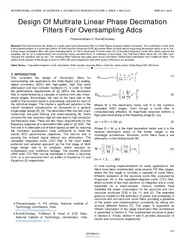
ijstror g Design Of Multirate Linear Phase Decimation Filters For Oversampling Adcs Phanendra abu H ArvindChoubey Abstract This brief presents the design of a audio pass band decimation filter for Delta Sigma analog to digital converters The contribu ID: 74213

ijstror Design Multirate

Share:

Link:

Embed:

Download Presentation from below link

Download Pdf The PPT/PDF document "INTERNATIONAL JOURNAL OF SCIENTIFIC TEC..." is the property of its rightful owner. Permission is granted to download and print the materials on this web site for personal, non-commercial use only, and to display it on your personal computer provided you do not modify the materials and that you retain all copyright notices contained in the materials. By downloading content from our website, you accept the terms of this agreement.


Presentation Transcript

INTERNATIONAL JOURNAL OF SCIENTIFIC & TECHNOLOGY RESEARCH VOLUME 2 , ISSUE 5 , MAY 2013 ISSN 2277 - 8616 210 IJSTR©2013 www.ijstr.or g Design Of Multirate Linear Phase Decimation Filters For Oversampling Adcs Phanendra b abu H, ArvindChoubey Abstract : This brief presents the design of a audio pass band decimation filter for Delta - Sigma analog - to - digital converters. The contribution of this work is the implementation of a multi - rate system of Finite Impulse Response (FIR) decimation filters of linear pha se supporting decimation ratios of 32 to 128. A three - stage decimation filter with down - sampling factor of 128 is developed. A fourth - order CIC (Cascaded Integrator - Comb) filter which reduces the sampling rate by 32 is implemented non - recursively using cas caded form of realization in first stage. Two half band filters follow the CIC filter each reducing the sampling rate by two. The resulting filters features less pass band droop and higher folding - band attenuation than traditional filters. The system level analysis of the design is done on MATLAB and comparisons with other works in literature are provided. Index Terms — Cascaded integrator comb, decimation, finite impulse response filters, multi - rate, linear phase, Delta - Sigma ADC Minimum ——————————  ——— ——————— 1. I NTRODUCTION This considers the design of Decimation filters for oversampling rate applications like Delta - Sigma ∑ analog - digital converters (ADC) with high - speed, high stop band attenuation and less complex hardware [1]. In order to meet the erformance requirements of ∑ ADCs, the decimation filter is implemented a s a cascade of several multi rate, linear - phase stages. Accordingly, the ratio of the input rate to the width of the transition band is dramatically reduced for each of the individual stages. This implies a significant reduction in the overall hardware com plexness as compared to a general single - stage design [2], [3]. The decimation filter has two major functioning: low - pass filtering and down - sampling [4], finally converts the low resolution high bit - rate data to high resolution low - frequency data. There a re two major requirements for the frequency resonse of a decimation filter used in ∑ ADC. The first one is to attenuate out - of - band signals as well as reducing the modulator quantization noise sufficiently to meet the overall ADC performance objectives. The second one is passing the in - band signal without any attenuation. The cascaded integrated comb (CIC) filter is the most widely preferred and adopted approach as the first stage of Multi stage design due to its simplicity, which requires no multiplication and coefficient storage. The transfer function of Kth order CIC filter can be expressed in either a recursive form, or a non - re cursive form as written in Equations (1) and Equations (2) respectively: (1) (2) Where M is the decimation factor and K is the numbers cascaded SINC stages. Even though a comb filter is computationally effective, its magnitude response exhibits a high ass band droo in the frequency range [0, ωc], ωc  π /D  π /M. ρ, (3) Where D  M. ρ is the total decimation factor and ρ is the residual decimation factor of the further stages in the multistage architecture. Moreover, comb filters have a low attenuation in the folding bands Wi, (4) for i  1, 2, .., M/2 In most existing implementations for audio applications, the filters have been implemented using several FIR filter stages, where the first stage is normally a cascade of comb filters. Efficient realisation of the recursive comb filter proposed by Hogenaue r [4] is the cascaded - integrator - comb (CIC) filter, which consists of two main sections: an integrator and a comb, separated by a down - sampler . Various methods have modelled the power consumption of the recursi ve and non - recursive structures [5 - 6] in Eq. (1) and ( 2) . The e xtended previous models for the estimation of power and complexity of recursive and non - recursive comb filters providing a guideline of the power and implementation complexity by taking into account different factors [7] . This paper is or ganized as follows: Description of two stage Decimation filter architecture is presented in Section 2. The Implemented structure is given in Section 3. Finally, section 4 and 5 provides discussion of results and conclusions respectively. ___________________________  Phanendrababu H, PG scholar, National Institute of Technology, Jamshedpur, India. phaniharimanikyam@gmail.com  ArvindChoubey, Professor & Head of ECE Dept., National Institute of Technology, Jamshedpur, India. achoubey.ece@nitjsr.ac.in INTERNATIONAL JOURNAL OF SCIENTIFIC & TECHNOLOGY RESEARCH VOLUME 2 , ISSUE 5 , MAY 2013 ISSN 2277 - 8616 211 IJSTR©2013 www.ijstr.or g 2. T WO STAGE DECI MATION FILTER The advantage of a multi - stage decimation filter is that a sharp low - pass filter must be realized only at the last stage. In addition, the follow - on FIR filters operate at reduced clock rates minimizing power consumption in high - speed hardwar e applications. The simplest architecture of the decimation filter is the CIC filter followed by another FIR filter. A linear - phase two - stage decimate - by - 128 filter with identical architecture was developed in [2]. The system diagram of such a filter is de picted in Fig. 1. CIC filters are an excellent choice for the first stage of decimation due to their simple implementation; however, additional care must be taken in the design stage to limit their order. Implementing a high - order CIC filter combined with the large decimation factor requires a high intermediate word length. Since CIC filters operate at the highest frequency, their power consumption is accordingly increased considerably. Consequently, it is preferred to design a low - order CIC filter to save power, by using fewer bits in higher frequencies. Decimation filters reported in [2 ], [8] and [9] employ high order CIC filters which are generally undesirable. The Frequency response of M - times averaging CIC filter includes succeeding zeros at fs/M interv als. After M - times down - sampling, these zeros fold back over zero frequency. Any signal in the band Wi, get aliased in the desired pass band. The attenuation offered by the CIC filter in these intervals should be ideally infinity that is gain should be zer o; these intervals are denoted as null intervals or folding bands, because after the Down Sampling by a factor of M, only the spectrum in the null intervals folds inside the desired signal bandwidth. The remaining stop band intervals are called as free int ervals. The following stages of CIC filter takes care of attenuating these folding bands further. In practical applications, only the frequency response of the first stage of the decimation filter can be relaxed. Fig.1. System diagram of a two - stage decimation filter Examining the overall frequency response of a multi - stage filter is a major challenge and additional care must be taken at design time. For example, one should filter and then down - sample rather than down - sampling and then filtering [10 ]. A multi - rate filter and its equivalent single - rate filter is shown in Fig. 2. (a) (b) Fig. 2. (a) Block diagram of a multi - stage multi - rate decimation filter (b) Block diagram of its single rate equivalent (a) (b) Fig. 3. (a) Direct Recursive f orm Implementation of order four CIC filter (b) Hogenauer Implementation To efficiently perform the decimation a two - stage decimation filter was used in [2] and [9]. A multi stage comb filter was developed using Hogenau er architecture [4] in which the actual transfer function is implemented in two steps. In step one, accumulation operations are performed and then signal is down sampled by factor M before doing the Subtractions, as depicted in Fig. 3 (b). The disadvantage with the Hogenauer architecture is the first stage accumulators works at very high oversampling rate which is power consuming. A bit - serial finite impulse response (FIR) filter was used for the second stage hich decimates the signal further by factor ρ. In the decimation filter design the last stage must be a sharp low - pass filter for which the order of the filter need is very high. The next session discusses the actual implementation in which two half band filter stages are used following the cascaded FIR implementation of CIC filter. 3. T HREE STAGE DECIMATIO N FILTER For this design, a linear phase, decimation by 128 filter was dev eloped with minimum stop band attenuation of - 50dB to the maximum attenuation above - 150 dB and less than .0003 dB pass band ripple. The pass band is specified from DC to 21.6 kHz, and the transition band from 21.6 kHz to 29.36 kHz. The implemented archite cture shown in F ig. 4 has two interesting features. Firstly, all the stages are implemented non - recursively hence the linear phase response is ensured. Secondly two half band filter stages, each decimating by factor two are used following the CIC filter, which reduces the hardware and power and hence simplifies the design. Fig. 4 . Architecture of implemented decimation filter 3. 1 . Stage - 1 CIC filter Design Generally, the mostly preferred CIC filter as a first stage of multistage decimation filter design has to work at oversampling rate and perform the majority of Decimation. In this design, a 4th order comb filter is designed to perform the decimation by 32. The transfer function H (z) of this comb filter is (5) In many of the earlier works CIC filter stage was implemented INTERNATIONAL JOURNAL OF SCIENTIFIC & TECHNOLOGY RESEARCH VOLUME 2 , ISSUE 5 , MAY 2013 ISSN 2277 - 8616 212 IJSTR©2013 www.ijstr.or g using Hogenauer structure, which resembles an FIR stage followed by IIR stage. To ensure the stability the minimum word length needed at the output of the first stage is (bin+log232), where bin is the number of bits at the input of the decimation filter. The major demerit of the Hogenauer structure is that the IIR filter stage, which performs acc umulation, is operated at oversampling frequency and hence drastically consumes the power. To decrease the power consumption, the comb filter is designed multistage, cascaded FIR filters, each stage performing decimation by a factor two as in [9]. From [9] the equation of the transfer function of the structure is (6) Fig. 5. CIC filter implementation as cascaded FIR decimating by 2 The structure is illustrated in Fig. 5. In this architecture, the comb filter is accomplished by cascading log232 = 5 similar FIR filters (1+z - 1)4, each decimating by 2. This way of designing CIC filter has the merit of avoided instability and the ord length of the each stage ‗i‘ limited bin  4 * i bits. The magnitude response o f the 4th order cascaded FIR comb filter is shown in Fig . 6 (a) .The cascaded FIR comb filter also results in a small amount of in - band droop that must be compensated in the end stages. 3.2 . Two Half - Band Filter St ages The used fourth - order CIC filter reduces the sampling rate by a factor 32. The remaining sampling rate reduction to the Nyquist output rate of 48 kHz is achieved efficiently with two cascaded half - band filter s. In the two half - band filters all , but one of the odd coefficients are zero, th ereby reducing the computational complexity by nearly 50% as compared to general direct - form filters architecture in [9]. This reduction, coupled with the symmetric property of the filter impulse response, allows it to be specified by number of coefficient s equal to only one fourth of the order of the filter. These half - band filters also compensate droop in the pass band of CIC stage to some extent. (a) (b) Fig. 6. (a) The frequency response of CIC filter (b) The combined frequency response of the Half - Band filters The first half - band filter is chosen to have a wide transition band. A tenth order half - band filter that has a stop band attenuation of 60 dB is chosen. This filter operates with the clock frequency of 192 kHz. The aliasing band lies in the region 72 kHz to 96 kHz. The second half band filter is the most stringent one as the means of meeting the requirements on magnitude response, which is reflected in its considerably increased order compared to the other stages. The second half - band fil ter provides the final filtering before the signal is down sampled to its Nyquist rate (48 kHz). The filter is designed to have a narrow transition band and a stop band attenuation of 50 dB. A fiftieth order filter is chosen. This filter operates with the clock frequency of 96 kHz. The aliasing band lies in the region 24 kHz to 48 kHz. INTERNATIONAL JOURNAL OF SCIENTIFIC & TECHNOLOGY RESEARCH VOLUME 2 , ISSUE 5 , MAY 2013 ISSN 2277 - 8616 213 IJSTR©2013 www.ijstr.or g TABLE 1 ATTENUATION OFFERED BY DIFFERENT STAGES OF DECIMATION FILTER CIC filter Half Band Filter Stage1 Half Band Filter Stage2 - 45 dB - 50 dB - 62 The combined frequency response of the first and the second half - band filters are shown in Fig. 6(b) . The magnitude of the frequency response of the overall filter is shown in Fig. 7 , which depicts the minimum attenuation in the first folding band is - 60dB and attenuations below - 140dB in farther folding bands of Stop band . The attenuations offered by the individual stages are given in Table1. This approach also permits the realization of decimation factors D= 32, 64 and achieved 16 bit resolution with Signal - to - Quantization nois e ratio 108dB . Fig. 7 . The overall frequency response of the decimation filter 4. S IMULATED RESULTS AND COMPARISON The proposed decimation filter has been designed and compared with the results of Decimation filter proposed in [9]. The design improvement is obtained by using two stages of Half - band filters each or order 10 and 50 respectively instead of using a single 55th order FIR filter down sampling by factor The use of Half - band filters simplifies the hardware requirement in the form of M ultipliers needed. Results of orders of the filters are included in Table1. The attenuation offered by the two half - band filters in the folding bands is much higher than Singles Stage FIR filter in afore mentioned one. The comparison of attenuations offere d is given in Table2.The decimation filter here implemented is providing the SNR of 108 dB which can achieve 16 bits of accuracy. The implemented architecture of decimation filter simplified the hardware with better stop band performance. TABLE 2 ORDERS OF DIFFERENT STAGES OF DECIMATION FILTER Filter CIC filter FIR filter Stage Half BandFilters [9] 4 55 Not used Proposed 4 Not used 10 50 TABLE 3 MINIMUM ATTENUATIONS OFFERED BY DIFFERENT STAGES OF DECIMATION FILTER Filter CIC filter FIR filter Stage [9] - 45dB - 45 dB Propose d - 45dB - 62 dB 5. C ONCLUSION In this work, betterments in the choice of decimation stages after CIC filter stage are provided by using Half - band filters. The entire analysis of the design was performed at a system level using Matlab. The use of multi - stage architecture comprising o f CIC and half - band filters has reduced the number of arithmetic computations and order requirements of the individual half - band filter stages. The implemented design also achieved improvement in attenuation of folding bands compared to previous published work [9] . The further improvement in the performance can be achieved by using effective droop compensation filter stage. R EFERENCES [1]. R. Jiang, and T. S. Fiez, "A 14 - bit AL ADC with 8x OSR and 4 - MHz conversion bandwidth in a 0.18 - tm CMOS process," IEEE J. Solid - State Circ., vol. 39, no. 1, pp. 63 - 74, Jan. 2004. [2]. I. Fujimori, K. Koyama, D. Trager, F. Tam, and L. Longo, "A 5 - V single - chip delta - sigma audio A/D converter with 111 dB dynamic range," IEEE J. Solid - State Circ., vol. 32, no. 3, pp. 329 - 336, March 1997. [3]. Brian P. Brandt, and Bruce A. Wooley, "A low - power, area - efficient digital filter for decimation and interpolation," IEEE J. Solid - State Circ., vol. 29, no. 6, pp. 679 - 687, June 1994. [4]. E. Hogenauer, ―An Economical Class of Digital Filters for Decimation and Interolation,‖ IEEE Transactions Acoustic, Speech and Signal Processing,vol.ASSP - 29, Apr.1981, pp.155 - 162. [5]. Y. Gao et al., ―A Comarison Design of Comb Decimators for Sigma - Delta An alog - to Digital Converters,‖ Analog Integrated Circuits and Signal Processing,No.22, 1999, pp.51 - 60. [6]. H. Aboushady at al., ―Efficient Polyhase Decomosition of Comb Decimation Filters in Sigma Delta Analog - to Digital Converters,‖ IEEE Trans. On Circuits and Systems II, vol.48, No10, 2001, pp.898 - 905. INTERNATIONAL JOURNAL OF SCIENTIFIC & TECHNOLOGY RESEARCH VOLUME 2 , ISSUE 5 , MAY 2013 ISSN 2277 - 8616 21 4 IJSTR©2013 www.ijstr.or g [7]. M. Abbas, O. Gustafsson, and L. Wanhammar, ―Poer Estimation of Recursive and Non - Recursive CIC Filters Implemented in Deep - Submicron Technology,‖ Proc. IEEE Conference ICGCS 2010,Shangai, China, June 2010, pp.221 - 225. [8]. T. Ritoniemi, et al, "A stereo audio sigma - delta AD - converter," IEEE J. Solid - State Circ., vol. 29, no. 12, pp. 1514 - 1523, Dec. 1994. [9]. Li Hongqin― Digital Decimation Filter Design and Simulation for Delta - Sigma ADC ith High Performance,‖ Pro c. IEEE Conference ICASIC 2007, Shangai, July 2007, pp. 922 – 925. [10]. SH. Chu, and C. S. Burrus, "Multirate filter designs using comb filters," IEEE Trans. Circuits Syts., vol. CAS - 3 1, no. 11, pp. 913 - 924, Nov. 19.