/
Oven Controlled Crystal Oscillator Oven Controlled Crystal Oscillator

Oven Controlled Crystal Oscillator - PDF document

lois-ondreau
lois-ondreau . @lois-ondreau
Follow
393 views
Uploaded On 2015-09-18

Oven Controlled Crystal Oscillator - PPT Presentation

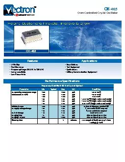
OX405 Vectron International x2022 267 Lowell Road Hudson NH 03051 x2022 Tel 188VECTRON1 x2022 httpwwwvectroncom 4Pin Dip Fast Warmup Frequency Range 80 MHZ to 120 MHZ Low gsen ID: 132719

OX-405 Vectron International 267 Lowell

Share:

Link:

Embed:

Download Presentation from below link

Download Pdf The PPT/PDF document "Oven Controlled Crystal Oscillator" is the property of its rightful owner. Permission is granted to download and print the materials on this web site for personal, non-commercial use only, and to display it on your personal computer provided you do not modify the materials and that you retain all copyright notices contained in the materials. By downloading content from our website, you accept the terms of this agreement.


Presentation Transcript

OX-405Oven Controlled Crystal Oscillator 4-Pin DipFast Warm-upFrequency Range: 80 MHZ to 120 MHZLow g-sensitivityLow Phase NoiseBase StationsTest EquipmentSynthesizersMilitary Communication EquipmentFeaturesApplicationsOX-405 Frequency Stabilities (SC-Cut Crystal-Option)ParameterMinTypicalMaxConditionvs. operating temperature range (referenced to +25°C)-40 to +85°C-20 to +70°C-0 to +70°C-40 to +85°C (height code 0 and 3 only)-20 to +70°C (height code 0 and 3 only)-0 to +70°C (height code 0 and 3 only)Initial tolerancevs. supply voltage changevs. load changevs. aging/dayvs. aging/1st yearat time of shipment, nominal EFC±5% static (CMOS outputs)±5% static (sine outputs) Performance Specications Performance Specications Supply Voltage (Vs)ParameterMinTypicalMaxConditionSupply VoltagePower ConsumptionWattsWattsWattsduring warm-up (5V versions)during warn-up (3V version)steady state @ +25°CRF OutputSignal [Standard]LoadSignal Level (Vol)with Vs=5V and 15 pF LoadSignal Level (Voh)with Vs=5V and 15 pF LoadSignal Level (Vol)with Vs=3.3V and 15 pF LoadSignal Level (Voh)with Vs=3.3V and 15 pF LoadDuty Cycle@ (Voh-Vol)/2Sinewave (5V supply, height code 0 or 3 only)LoadOutput Power @ 5VHarmonicsFrequency Tuning (EFC)Tuning RangeLinearityTuning SlopePositiveControl Voltage Range5 V versions3.3 V versionsAdditional ParametersPhase NoisedBc/HzdBc/HzdBc/HzdBc/HzdBc/Hz10 Hz100 Hz1 kHz10 kHz100 kHz@ 100MHzG-Sensitivityworst direction - standardworst direction - request a custom partWeightAbsolute Maximum RatingsSupply Voltage (Vs)Output LoadOperable Temperature RangeEnvironmental and Product ClassicationShock (Endurance)MIL-STD-202, Method 213, Condition J, 30 g 11 msSine Vibration (Endurance)MIL-STD-202, Method 201 and 204, Condition A, except 5 g to 500 Hz, 1 sweep each axisRandom Vibration (Endurance)MIL-STD-202, Method 214, Condition I-DHumidityMIL-STD-202, Method 103, Condition B, 100% rhSealMIL-STD-202, Method 112, Condition DAltitudeMIL-STD-202, Method 105, sea level to spaceResistance to Soldering HeatMIL-STD-202, Method 210, Condition A,B,CTerminal StrengthMIL-STD-202, Method 11, Condition C (5 bends at 45Moisture Sensitivity levelROHS ComplianttYesStorage Temperature Range Performance Specications Outline Drawing / Enclosure Dimensions in inches (mm) Type ACodeHeight “H”Pin Length “L” MinPin ConnectionsElectronic Frequency Control Input (EFC)Ground (Case)RF OutputSupply Voltage Input (VS) Type B CodeHeight “H”Pin Length “L” MinPin ConnectionsElectronic Frequency Control Input (EFC)Ground (Case)RF OutputSupply Voltage Input (VS) Standard Shipping Method Enclosure TypeTape width W [mm]Quantity per meterQuantity per reelType B Recommended Reow Prole Ordering Information OXD Product FamilyOX: OCXO Package Height0: A9.3 mm (THT)1: A8.3 mm (THT)2: B10.4 mm (SMD)3:B11.4mm (SMD) Supply Voltage Stability Code508: ±50ppb (height code 0 and 3 only)358: ±35ppb (height code 0 and 3 only)258: ±25ppb (height code 0 and 3 only) Frequency Frequency Control0: No Tuning2: ±1.0 to ±3ppm Rev: 5-2-2019 jar RF Output CodeE:Sinewave (height code 0 and 3 only) Temperature RangeE: -40°C to +85°CJ: -20°C to +70°CT: 0°C to +70°C Notes:Contact factory for improved stabilities or additional product options. Not all options and codes are available at all frequencies.Unless other stated all values are valid after warm-up time and refer to typical conditions for supply voltage, frequency control voltage, load, temperature (25°C).Phase noise degrades with increasing output frequency.Subject to technical modication.Contact factory for availability.G Sensitivity - standard parts will be delivered at 1 ppb/g If 0.5ppb/g is requested please contact the factory and a custom part number will be assigned Contact InformationUSA:100 Watts StreetMt Holly Springs, PA 17065Tel: 1.717.486.3411Fax: 1.717.486.5920Europe:Landstrasse74924 Neckarbischofsheim GermanyTel: +49 (0) 7268.801.0Fax: +49 (0) 7268.801.281Information contained in this publication regarding device applications and the like is provided only for your convenience and may be superseded by updates. It is your reasonability to ensure that your application meets with your specications. MICROCHIP MAKES NO REPRESENTATION OR WARRANTIES OF ANY KIND WHETHER EXPRESS OR IMPLIED, WRITTEN OR ORAL, STATUTORY OR OTHERWISE, RELATED TO THE INFORMATION INCLUDING, BUT NOT LIMITED TO ITS CONDITION, QUALITY, PERFORMANCE, MERCHANTABILITY OR FITNESS FOR PURPOSE. Microchip disclaims all liability arising from this information and its use. Use of Microchip devices in life support and/or safety applications is entirely at the buyer’s risk, and the buyer agrees to defend, indemnify and hold harmless Microchip from any and all damages, claims, suits, or expenses resulting from such use. No licenses are conveyed, implicitly, or otherwise, under any Microchip intellectual property rights unless otherwise stated. TrademarksThe Microchip and Vectron names and logos are registered trademarks of Microchip Technology Incorporated in the U.S.A. and other countries.