/
1 Making Cables for the 8-ch C13 Rat  Array 1 Making Cables for the 8-ch C13 Rat  Array

1 Making Cables for the 8-ch C13 Rat Array - PowerPoint Presentation

luanne-stotts
luanne-stotts . @luanne-stotts
Follow
388 views
Uploaded On 2015-11-09

1 Making Cables for the 8-ch C13 Rat Array - PPT Presentation

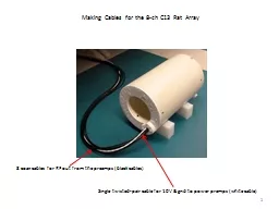
8 coax cables for RF out from the preamps black cables Single twistedpair cable for 10V amp gnd to power premps white cable 2 Overview Making JST Power Cables Making Radiall SMP Coax Connections ID: 187871

making cable pin wire cable making wire pin crimp coax plug smp outer connections tool series solder power hypertronics

Share:

Link:

Embed:

Download Presentation from below link

Download Presentation The PPT/PDF document "1 Making Cables for the 8-ch C13 Rat Ar..." is the property of its rightful owner. Permission is granted to download and print the materials on this web site for personal, non-commercial use only, and to display it on your personal computer provided you do not modify the materials and that you retain all copyright notices contained in the materials. By downloading content from our website, you accept the terms of this agreement.


Presentation Transcript

Slide1

1

Making Cables for the 8-ch C13 Rat Array

8 coax cables for RF out from the preamps (black cables)

Single twisted-pair cable for 10V & gnd to power premps (white cable)Slide2

2

Overview

Making JST Power CablesMaking Radiall SMP Coax Connections

Making Smiths/Hypertronics N series Mod K Coax ConnectionsMaking Smiths/Hypertronics N series Mod V Signal Connections

Making Cable TrapsSlide3

3

Whether your scanner is a GE, Siemens, Philips, Bruker, etc., the far end of the cable that plugs into the scanner will have proprietary connections. As a researcher at an institution that has access to proprietary information (one that has signed a research agreement, a legal document), you have to be aware to not divulge any of those companies’ intellectual property.

Those companies typically buy their connectors from 3

rd

party connector companies and/or have special parts made for them (of special non-magnetic, non-contaminated plating alloys, etc.). There are many such connector companies (ODU, Smiths/Hypertronics, Huber & Suhner and so on.)

These slides won’t go over any proprietary connections, but rather simply go over the mechanics of making crimp connections of a few types of relevant connectors, so that you can fix your cables if/when they break. When most complicated pieces of equipment do break, it’s usually the connectors that have gone bad. Slide4

4

Mechanical (only) guide posts for alignment

Coaxial connectors for RF out from each coil in the array

Single-wire connectors for low-frequency control signals and power/gnd

An ID chip (EEPROM), similar to the ID chips for printer toner cartridges

Plastic case is mostly cosmetic, but can be useful to provide strain relief during handling

A Typical MRI Scanner ConnectorSlide5

5

Of course, on your end of the cable, you can design with whatever connectors you like. Here we use JST 2-pin connectors for power/gnd, and Radiall’s SMP miniature coax connectors for RF signals.

No connectors are used between the coil and the preamp board. We simply solder/unsolder the coil neck ends to two pads on each preamp board.

JST 2-pin power conns

Radiall SMP coax connsSlide6

6

Overview

Making JST Power CablesMaking Radiall SMP Coax Connections

Making Smiths/Hypertronics N series Mod K Coax ConnectionsMaking Smiths/Hypertronics N series Mod V Signal Connections

Making Cable TrapsSlide7

7

JST SFHR-02V-R

JST SSFH-001T-P0.5

JST WC-SFH1

JST SM02B-SFHRS-TF(LF)(SN)

Using 26 AWG stranded wire (Alpha Wire #3049), available from Mouser. Contact JST to ask for crimping instructions and strip length. JST, like most connector vendors, does not post crimping instructions on their web site.Slide8

8

Important! Make sure that whether you choose #22, #24 and #26 wire, that you choose one with an outer diameter less than 1.3 mm!Slide9

9

Make sure to check the datasheet for the wire you use or measure the outer diameter. This

Alpha Wire (#

3049) 26 AWG wire’s outer diameter is just barely less than 1.3 mm. Similar 24 AWG wire that I tried was too large and the crimp didn’t work (the cable fell apart). Check the manufacturer’s web site for datasheets, before you buy wire.Slide10

10Slide11

11Slide12

12

Use diagonal cutters that have a flush backside and pointy tips: Xcelite (Digikey #MS543JV)...

...to snip the stripped length to 1.7 mm:Slide13

13

1.7 mmSlide14

14

A proper crimp should come out looking like this:

The stripped length should be precisely 1.7 mm so that the wire strands end here, below where the mating pin will reach:

This lower tang should grab the insulation.

This upper tang should grab solely stripped metal.Slide15

15

The crimp tool is designed to crimp these lower 2 tangs around your wire.

These bend-overs won’t be changed by the crimp tool. This bend-over is what accepts the mating pin that’s in the receptacle that this plug will plug into.Slide16

16Slide17

17Slide18

18

If you simply hold your ~1.7 mm length of stripped wire up to the contact which is sitting in the back flap, you can see if the strip length is correct. The outer tang should be able to grab onto the insulation, so the outer tang should come to about this position on your wire:Slide19

19

Now, with the contact in the back flap’s hole marked 26 AWG, fold up the back flap ...

...

f

rom the front, the contact looks like this:Slide20

20

Carefully, insert the wire all the way in, making sure the outer tang will be able to grab the insulation. Then squeeze until the handles spring back.

Notice, that as you gradually release, you can’t actually get your crimped wire out now ...Slide21

21

To get your crimped wire out, you now have to tilt the back flap back a few degrees ...

...

n

ow you can pull it out. Slide22

22

These pins are positioned towards the top of this board-mount connector, so this contact has to have this part that slides over that pin, oriented towards the top also, when we slide it into the plug.

Top surface

Plug top surfaceSlide23

23

...

o

r here’s another way of saying it:Slide24

24

On the preamp board and on the power distribution ribbon, I defined the leftside pin as ground.

Here we’ll use black as the color of the wire to be connected to ground. Slide25

25

Plug bottom surface

This tang orients towards the bottom and latches.

Plug top surface (top is flatter than the bottom)Slide26

26

The board footprint is laid out for this lead to be +10 V.

Ground

This front lead and the one on the far side are just for mechanical attachment to the board. They aren’t connected to the internal pins.Slide27

27

On the power distribution ribbon, the yellow connector is where the cable will bring 10 V and ground to this power ribbon.

Then the power distribution ribbon has a separate red power connector for each preamp board. For each preamp board, we need to make a power cable to connect here and here:Slide28

28

Think first, before inserting the contacts into the other plug. The way the boards are laid out, we need this way:Slide29

29Slide30

30Slide31

31

Always ohm-out power and ground connections after you make power cables. Make sure ground and one board is connected to ground on another board. Check 10 V locations on each board. Make sure a 10 V location is not connected to ground, etc. Don’t skip this step. It’s not worth it (the preamps are $145 each and have a 6-week lead time).Slide32

32Slide33

33

Overview

Making JST Power CablesMaking Radiall SMP Coax Connections

Making Smiths/Hypertronics N series Mod K Coax ConnectionsMaking Smiths/Hypertronics N series Mod V Signal Connections

Making Cable TrapsSlide34

34

SMP right-angle plug

SMP separation tool

SMP surface-mount receptacle

(sends RF_out from the preamp to the scanner cable)

SMP coaxial connectors:

Once the plug and receptacle are mated, we need a special SMP separation tool to get them apart.

To scanner

First though, we need to attach the SMP right-angle plug to a piece of coax cable ...

To probe coil Slide35

35

How do we attach the SMP right-angle plug (this SMP plug is made for RG-316 coax) to the cable?

When you buy this connector (Radiall #R222.900.357W), it comes with a ferrule and a cap:

ferrule

capSlide36

36

Radiall R222.900.357W SMP (non magnetic) right angle plug

http://www.radiall.com/media/files/NonMagnetic%20D1C004XEe.pdf

5

mm

1.5 mm

1.3 mm

First, strip the (non-magnetic) RG-316 coax to these dimensions:Slide37

Elspec non-magnetic RG316 coaxial cable:

37Slide38

38

Kingsing KS-09S coax stripper

www.kingsing.sh

Parameters for coax stripping

RG316 for SMP plugs:Step 1: Strip length 2.8 mm

Wire dia 1.25 mm Wire drawback 4 mm

Blade wayback

0.1

mm

Cut time 1 sec

Rotary twist 0 (no)

Step 2:

Strip length

1.3

mm Wire dia 0.5 mm Wire drawback

4 mm Blade wayback 0.1 mm Cut time 1 sec Rotary

twist 1 (yes)Step 3: Strip length 7.8 mm Wire dia

2.15 mm Wire drawback 10 mm Blade wayback 0.1

mm Cut time 1 sec Rotary strip 0 (no)

Hint: use a vise grips (Quick-Grip with rubber jaws) to hold ontoSlide39

39

Radiall R222.900.357W SMP (non magnetic) right angle plugSlide40

40

Note: slide the ferrule onto the wire before flaring the braid! Don’t forget this step!

I use a sharp scalpel’s point to gently flare the braid. Since this particular coax cable from Elspec has an inner foil, sometimes you need to slice it in order to flare it out.Slide41

41

Outer conductor goes outside the knurled shaft of the SMP plug

Inner conductor slides over top this gold post inside the plastic insulator:

Inner conductor

The crazy part is that we actually need to solder the inner conductor to that gold piece ... But that’s a later step. First, we need to crimp the outer conductor ...

Plastic insulation surrounding gold postSlide42

42

Radiall R222.900.357W SMP (non magnetic) right angle plug

Daniels crimp frame HX4

Daniels die set Y196, cavity A

...for the outer crimp of the Emerson SMA bulkhead-cable jack, #142-9303-411

Y196 cavity ASlide43

43

Slide the ferrule down over the outer braid. The ferrule is what we’re crimping to the knurled shaft:Slide44

44

Now that we’ve connected the outer braid of the cable to the outer shell of the SMP plug, we next have to connect the cable’s inner conductor to the SMP plug’s signal pin. This means we have to solder this inner conductor to this gold post:

The only chance of soldering this sucessfully is if you have a beveled tip like this. The “bevel” means is has a flat edge here:

W

e’ll put that flat edge so it contacts both the inner conductor and the gold post, so as to heat them simultaneously.Slide45

45

Also, there is absolutely no chance to be successful unless you apply flux. Flux is the magical chemical that makes soldering work. The soldering process is a highly engineered system – flux is corrosive and gets rid of the oxide, allowing the two metal surfaces to get soldered together:Slide46

46

After applying flux, heat both the inner conductor and the gold post at the same time:Slide47

47

Then bring in a bit of solder (if you’re using lead-free solder, you need to use flux made for lead-free solder).

There is no chance to get this to work unless you sit down and fixture your arms and hands against the desk, and the vise, using your palms and wrists to wrap around the vise:Slide48

48

It should end up like this – a solder fillet on top of the gold post, with no solder shorting to the sides of the aluminum cavity:Slide49

49

Verify that there is no solder shorting the inner conductor to the outer shell, by ohming them out. You can also ohm out the opposite end of the cable to check.Slide50

50

Next, press-fit the SMP plug’s cap:Slide51

51Slide52

52

With the cap on, there is no danger that a piece of dirt will fall in there and short the inner conductor to the cavity:Slide53

53

SMP plugs have this moveable ring that has a slot. When you push this plug into its mating receptacle, this ring gets forced upwards (by the mating receptacle) towards the aluminum block and tightens, making a very good connection, yet allows for rotation:Slide54

54

When inserting the plug into its mating receptacle on a board, be careful. You don’t want to break or bend this pin. The goal of a good coax connection is to have a perfect 50 ohm transmission line, without any reflections of the wave when it sees the connector. Check for dirt or dust in the receptacle. Blow out with clean dry air. Also, use a gage on both the plug and the receptacle after you’ve crimped the plug and soldered the receptacle (to check that they connectors weren’t mangled during the assembly processes). Slide55

55

The non-magnetic

surface-mount mating receptacle is Radiall #

R222941324w.

These SMP connectors are precision, expensive, high-quality connectors. Put them together carefully. Make sure the

b

oard is resting on a flat surface, and orient the top of the plug exactly perpendicular to the mating receptacle. Then push down with exactly an axial force (a lot of force, carefully applied), until they go together.

Hold horizontally

Apply force verticallySlide56

56

Push straight down until fully seated.

Now the tricky part is getting them apart. These are such good connectos, getting them apart is not straightforward...Slide57

57

Radiall R222.900.357W SMP (non magnetic) right angle plug

The extraction tool to remove this plug from its mating receptacle, R222941324w is:

R282.918.210

You have to use this special tool, and you have to sharpen it first...Slide58

58

This pry-bar edge looks like this when you buy the tool new. It’s not nearly sharp enough to pry the plug ring’s top edge down from the plug’s aluminum block.

You have to file the edge of this tool. Hold it in a vise and file the angled edge until it’s sharp.Slide59

59

Not filed sharp enough:

This edge needs to be *very* sharp, like this ...Slide60

60

You *must* hold onto the plug’s aluminum block (with your opposite hand):

...

b

ecause you need to insert the sharp tip into a difficult, tight space ... Slide61

61

The pry-bar tip needs to go flush against the plug’s aluminum block, between the aluminum block and the top of the plug’s ring.

Not between the plug’s ring and the mating receptacle!

The idea is to force down the plug’s ring using the thickness of the pry-bar, which in turn pushes the mating receptacle away from the plug.Slide62

62

It’s an indirect separation technique. You don’t even touch the mating receptacle!

Here’s another view of what you’re trying to do:Slide63

63

Only after you’ve separated the plug ring away from the plug’s aluminum block, do put the tool away and now gently (applying a vertical force) pull the mating receptacle away from the plug:Slide64

64

If the pry-bar wasn’t sharp enough, you’ll just be pushing against both surfaces and gouging them up. And they won’t come apart. The whole trick is to make a very sharp tool.Slide65

65

Overview

Making JST Power CablesMaking Radiall SMP Coax Connections

Making Smiths/Hypertronics N series Mod K Coax ConnectionsMaking Smiths/Hypertronics N series Mod V Signal Connections

Making Cable TrapsSlide66

66

These crimp contacts accept 22 AWG through 26 AWG stranded wire

N series Module K

Single-conductor (not coax) signal pinsSlide67

67

Google for the crimping instructions, S50063

:

(Also ask for the extraction instructions.Slide68

68

You can use the insertion tool to first push the pin all the way in, in this downward direction ...

Then use the extraction tool, sliding its tubular end over the pin’s tangs to squeeze the tangs together so they no longer catch on the latching bump.

T1970

S/DEM1.0060Slide69

69Slide70

70Slide71

71

Strip 0.173” (4.4 mm)

Use squeeze-n-strip wire strippers:Slide72

72Slide73

73

C

rimp tool frame

The AFM8 tool frame works with a variety of positioners. The positioners hold different crimp pins at different depths in the backside of the tool:

Pin positioners

(want the K547)

Remove the clip to swap positionersSlide74

74

Note listings here. The listings tell which setting of the crimp squeeze to use for different wire gauges. For 24 AWG, we want setting #4:

Pull out

this clip

and

rotate the black dial to setting #4. Slide75

75

Squeeze-n-strip ...

...

a

nd snip to 4.4 mm lengthSlide76

76

Flip the crimp frame over and insert the pin into the positioner:Slide77

77

Squeeze the handles lightly – don’t crimp all the way. You can see where the crimp teeth will bite into the pin: Slide78

78

Insert the stripped end of the wire into the pin, squeeze the handles until they spring back, and then remove the crimped pin:Slide79

79

Next, insert the pin into the plug’s insulating housing. Refer back to the crimping instructions and note the flats on the housing’s holes:Slide80

80

These flats on the left and right edges of the gold pin go into the black plastic rectangular holes in this orientation:

These flats on the left and right edges of the gold pin go into the black plastic rectangular holes in this orientation: Slide81

81

Overview

Making JST Power CablesMaking Radiall SMP Coax Connections

Making Smiths/Hypertronics N series Mod K Coax ConnectionsMaking Smiths/Hypertronics N series Mod

V Signal ConnectionsMaking Cable TrapsSlide82

82

Hypertronics (now Smiths Connectors)

Modular N series:

N series Module V male

coax connectors

Heat shrink tubing

Ferrule

Contact

Male pinSlide83

83

Hypertronics catalog

-

male

-female

Crimping Datasheet Number is listed on p. 4/35 of the catalog:

N series, Module V, NVMRTH w/male contacts, (magnetic version) YCX0315-004: p. 4/34.

These are the standard catalog part numbers (magnetic version). Call Hypertronics for the non-magnetic version.

Also ask for the crimping instructions.Slide84

84

To extract a Mod V contact, you need this tool

T1982

... and any 1/8” dia rod:Slide85

85

Push the back side of the contact all the way forward, and then slip the tube over the front of the contact, so that it pushes in the Slide86

86Slide87

87

If the tube has successfully pushed down the latches, then pushing on the plunger should push the contact out easily:Slide88

88

Smiths/Hypertronics’ ClearImage line of connectors are the non-magnetic versions of the N series modular connectors:

http://

www.hypertronics.com/en/Technology/HypertacTechnologies/ClearImage.aspx

Slide89

89

Daniels AFM8 crimp tool frame

Daniels K1246

positioner

Daniels HX3

crimp tool frame

Daniels 101

d

ie set (crosses with the T1958 called out). Use

c

avity A.

Use setting #5

For assembling the Mod V connector, you use 2 crimp tools, one for the inner conductor, and one for the outer conductor:Slide90

90

5.59 mm

2.54 mm

3.94 mmSlide91

Elspec non-magnetic RG316 coaxial cable:

91Slide92

92

Kingsing KS-09S coax stripper

www.kingsing.sh

Parameters for coax stripping for Hypertronics N series Mod V:

Step 1: Strip length 6.5 mm Wire dia 1.3 mm Wire drawback 10 mm

Blade wayback 0.2 mm Cut time 1 sec Rotary twist 0 (no)

Step 2:

Strip length

2.5

mm

Wire dia

0.5

mm

Wire drawback

4

mm

Blade wayback 0.1

mm Cut time 1 sec Rotary twist 1 (yes)Step 3:

Strip length 12.1 mm Wire dia 2.01 mm Wire drawback

15 mm Blade wayback 0.2 mm Cut time 1 sec Rotary strip 0 (no)Slide93

93

Use the AFM8 crimp frame with the T1957 (K1246) positioner. T1957 is the MIL-Spec standard number and K1246 is the manufacturer’s (Daniels Manufacturing) part number. Set the black dial to Setting #5:

The gold pin sits all the way down in the aluminum positioner:Slide94

94

Squeeze the handles lightly – don’t crimp all the way. You can see where the crimp teeth will bite into the pin:

With your RG-316 coax cable stripped to the correct length, insert the inner conductor all the way in, and crimp: Slide95

95

Release the handle and take out the crimped pin. If you look carefully, you can see where the teeth dug into the gold pin to crimp it. If you inserted the coax correctly into the positioner, the gold pin should butt up directly against the clear insulation:Slide96

96

Now, before moving on to crimping the outer conductor, don’t forget this step:

Slide the heat shrink tubing and the ferrule onto the cable first!

Ferrule

Heat shrink tubingSlide97

97Slide98

98

The contact has been inserted into the T2040 alignment tool.

However, before inserting the crimped center pin, we’ll need to flare out the stripped outer braid ...Slide99

99

Flare back the outer braid and its aluminum-foil shield (you might need to use a sharp surgeon’s scalpel to slice

f

oil so that you can flare it back. This outer conductor needs to go outside the gold, knurled shaft of the contact:Slide100

100Slide101

101

Hold the cable right here, to gently (but firmly) push in the pin:

Verify you’ve pushed the pin in all the way by looking at the tip of the pin from this angle. There is no gage kit for this connector, so you have to use this tool to confirm you’ve got the center pin at the correct depth. You’ll feel a snap-like latch when the center pin seats correctly into the contact. The pin should touchSlide102

102Slide103

103Slide104

104

The crimp instructions a few slides back called out the MIL-Spec standard part numbers for the appropriate crimp tool frame and die set to use for the outer contact’s crimp. The corresponding part numbers from the vendor are Daniel’s HX3 crimp frame and X101 die set. The crimp instructions also called out to use “Cavity A” for our RG-316 cable:Slide105

105

Slide the ferrule down over the outer braid which is now on top of the contact’s knurled shaft. The ferrule is what we actually crimp:Slide106

106

Now it’s crimped:Slide107

107

Now slide the heat shrink tubing over the crimped ferrule:

...and shrink the heat shrink tubing with a hot air gun:Slide108

108Slide109

109

Then label the cable and put it into the connector:Slide110

110

Once you’ve made the electrical connections for your cables, you need to add mechanical strain reliefs ...Slide111

111

Here’s a home-brew strain relief for a home-brew cable: machine a plastic ring, slide it over your cables and then shring heat shrink tubing over it. Carve out a slot in the housing where the shrink-covered plastic ring can sit:Slide112

112

That is, put thin heat shrink around the cable bundle, followed by the nylon spacer ring ... then put 4:1 shrinkable fabric heat shrink on the outside of the nylon spacer ring, and slip the whole spacer fin assembly into the milled slot. Slide113

113

Now you can tug in this direction all you want, and no stress gets applied to the electrical contacts.Slide114

114

Do something similar on the rat cylinder ...

c

reate a feature on the rat cylinder that serves the same purpose as the milled slot shown in the previous slides:Slide115

115

...

a

nd machine another plastic ring that you can pass over this far end of your cable. You’ll heat shrink thisring over the cable bundle and let it sit in this slot:Slide116

116

M

ove the heat-shrinked plastic ring

o

ver to sit in this pocket. Slide117

117

Then screw on the upper half of the bracket and you’ll have a good strain relief for this end of the cable.Slide118

118

Overview

Making JST Power CablesMaking Radiall SMP Coax Connections

Making Smiths/Hypertronics N series Mod K Coax ConnectionsMaking Smiths/Hypertronics N series Mod V Signal Connections

Making Cable TrapsSlide119

119

To make a cable trap, find some plastic tubing

(easy to slice if you have a laser cutter). Then design and 3D-print a simple spool that will fit in the tube. Wind your coax cable around the spool and slip the tube over the spool. Slide120

120

Then remove a small slice of the coax cable’s outer jacket on each end.Slide121

121

You can use a wire stripper to (gently) make the correct diameter cut, as shown on the previous slide ... or you can use a surgeon’s scalpel (put on a new sharp blade).Slide122

122

After stripping slices of the outer jacket, wrap the spool in copper tape.Slide123

123Slide124

124

Copper tape usually comes with a conductive adhesive on the back, but it’s best to add some solder to make a good contact. Always, always, always apply flux when soldering. Flux is the magic ingredient that makes solder work. If you use lead-free solder (what we typically use, since all components these days are plated with lead-free solder), make sure to use a flux designed for lead-free solder. The combination is a heavily-engineered systems by metallurgists. Slide125

125

To make a cable trap, one end of the spool’s RF shield gets soldered directly to the outer braid. Apply copper tape from the shield up to, and touching the braid.Slide126

126

The other end of the spool gets a capacitor soldered between the RF shield and the copper braid. Here, 256 pF made the outer braid’s inductance create a parallel resonance at the frequency for C13 imaging at 3 T (32 MHz). We used two non-magnetic ATC (series 100B) capacitors in parallel: 200 pF + 56 pF. Hold the two together in a pair of tweezer, apply flux and solder their ends together.

Then solder the capacitors onto the other end of the spool.

Hint: Tin the copper tape (apply flux first!) with some solder first. Then you can solder one end of the capacitor pair to that tined surface. Slide127

127

Then solder the other end of the capacitor pair to the outer braid:Slide128

128

Then measure the parallel resonance on a |S11| trace on the network analyzer, using a sniffer coil attached to Port 1.

Sniffer coil.

Ferrite cable trap for bench top testing.