/
Refraction Of Light & Optical Instruments Refraction Of Light & Optical Instruments

Refraction Of Light & Optical Instruments - PowerPoint Presentation

luanne-stotts
luanne-stotts . @luanne-stotts
Follow
403 views
Uploaded On 2018-03-17

Refraction Of Light & Optical Instruments - PPT Presentation

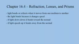
Chapter 14 SNELLS LAW     According to Snells law The ratio of the sine of the angle of incidence to the sine of the angle of refraction is always constant      Mathematically ID: 654170

image object lens eye object image eye lens objective piece length focal power angle position magnifying image

Share:

Link:

Embed:

Download Presentation from below link

Download Presentation The PPT/PDF document "Refraction Of Light & Optical Instru..." is the property of its rightful owner. Permission is granted to download and print the materials on this web site for personal, non-commercial use only, and to display it on your personal computer provided you do not modify the materials and that you retain all copyright notices contained in the materials. By downloading content from our website, you accept the terms of this agreement.


Presentation Transcript

Slide1

Refraction Of Light & Optical Instruments

Chapter 14Slide2

SNELL’S LAW

    According to Snell’s law

"The ratio of the sine of the angle of incidence to the sine of the angle of refraction is always constant. "

    Mathematically,

    Sine <

i

/sine <r = constant 

or

sin<

i

/sine< r = 

mew


where

mew

 = Refractive index of the material of medium.Slide3

TOTAL INTERNAL REFLECTION

    When light rays enter from one medium to the other, they are refracted. If we increase the angle of     incidence, angle of refraction will also increase. At certain angle of incidence light rays are reflected     back to the first medium instead of refraction. This condition or phenomenon is called Total Internal     Reflection.Slide4

CRITICAL ANGLE

    The angle of incidence at which the angle of refraction will become 90

o

 is called Critical Angle. If angle     of incidence further increased then instead of refraction, reflection will take place.Slide5

DEFECTS OF VISION

There are four common defects of vision:

    1. 

SHORT SIGHTEDNESS


OR MYOPIA

    2. 

LONG SIGHTEDNESS


OR HYPER METROPIA

    3. 

ASTIGMATISM

    4. 

PRESBYOPIASlide6

SHORT SIGHTEDNESS OR MYOPIA

SYMPTOMS


    In Myopia, a person can not see distant objects clearly, but he can see clearly the objects near to him.

REASON


    The reason for Myopia is either the focal length of lens of eye is too short or the eyeball is very much     elongated.

WHAT HAPPENS IN

MYOPIA


    In Myopia, light rays from a distant object are focused in front of the Retina.Slide7

CORRECTION OF DEFECT

This defect can be corrected by using a concave lens of suitable focal lengthSlide8

ASTIGMATISM - PRESBYOPIA

ASTIGMATISM

    If the cornea or the surface of eye is not perfectly spherical. In this situation the eye has different focal     points in different planes and an object is not focused clearly on the retina.

CORRECTION OF

DEFECT


ASTIGMATISM

 is corrected by using asymmetrical lenses which have different radii of curvature in     different planes

PRESBYOPIA

or

lack of

accommodating


    At old age, the eye lens loses its natural elasticity and ability to change its shape and the

ciliary

muscles     weaken resulting in a lack of accommodation. This type of long sightedness is called "

PRESBYOPIA

".

CORRECTION OF

DEFECT


This defect can be corrected by using convex lens for long sighted person and concave lens for short sighted person

.Slide9

LONG SIGHTEDNESS 

OR HYPER

METROPIA

SYMPTOMS

    In

 HYPER METROPIA

, a person can not see objects clearly which are near to him, but he can see clearly     distant objects

REASON

    The reason for 

HYPER METROPIA

 is that either the focal length of the lens of eye is too long or the     eyeball is too short.

WHAT HAPPENS

IN HYPER


METROPIA


    In 

HYPER METROPIA

, light rays from a near object are focused behind the Retina.Slide10

CORRECTION OF DEFECT

This defect can be corrected by using a convex lens of suitable focal lengthSlide11

POWER OF LENS

    Power of lens is defined as the reciprocal of the focal length of the lens in meters.


FORMULA:

Power = 1/f

(in meter)

    Unit of power of lens is

Dioptre

.

DIOPTRE


    Dioptre is defined as the power of lens whose focal length is one meter    if f =1 meter then the power of the lens = 1

dioptre

.Slide12

Image Formation by convex lens

POSITION OF OBJECT

When the object is placed at infinity


POSITION OF OBJECT

When the object is placed at infinity


NATURE AND POSITION OF IMAGE

1. 

The image will form at the principal focus (F).


2. 

The image will be real and inverted.

3. 

The image will be very small in size.Slide13

POSITION

OF OBJECT

When the object is placed beyond 2F


Nature and position of image

1

.

 The image will form between F and 2F. 

2.

 The image will be real and inverted.

3. 

The image will be smaller in size.Slide14

POSITION OF OBJECT

When the object is placed at 2F


NATURE AND POSITION OF IMAGE

1. 

The image will form at 2F. 

2. 

The image will be real and inverted.

3. 

The image will be equal in the size of object.Slide15

POSITION OF OBJECT

When the object is placed between F and 2F


NATURE AND POSITION OF IMAGE

1.

 The image will form beyond 2F. 

2. 

The image will be real and inverted.

3.

 The image will be magnified.Slide16

POSITION OF OBJECT

When the object is placed at F

NATURE AND POSITION OF IMAGE

1.

 The image will form at infinity. 

2. 

The image will be real and inverted.

3.

 The image will be highly magnified.Slide17

POSITION OF OBJECT

When the object is placed between the pole (P) and

F


NATURE AND POSITION OF IMAGE

1.

 The image will form on the same side of object. 

2. 

The image will be virtual and erect.

3.

 The image will be magnified.Slide18

ASTRONOMICAL TELESCOPE

Introduction

   It is an optical instrument used to view heavenly bodies such as

moon,stars

, planets and distant object.

Construction

   Astronomical telescope consists of two convex lenses:

1:

Objective


2:Eye

pieceObjective

   The objective is a convex lens of large focal length and large aperture. It usually made of two convex lenses    in contact with each other to reduce the chromatic and spherical aberrations.Slide19

Eye piece


 The eye piece is also a convex lens .Its focal length is smaller than that of objective. It is also a    combination of two lenses.

   The objective is mounted on a wide metallic tube while the eye piece is mounted on a small tube .The    distance b/w the eye piece and the objective can be changed by moving tubes.Slide20

WORKING

The rays coming from a distant object falls on objective as parallel beam at some angle say "

a

" and these    rays after refraction and passing through the objective converge at its focus and make an inverted & real    image 

AB. This

 image acts as an object for the eye piece. The distance of the eye piece is so adjusted that    the image 

AB

 lies within the focal length of the eye piece. The eye piece forms the final image .The final    image is magnified ,virtual and inverted with respect to object. The final image is formed at infinity.Slide21

WORKINGSlide22

MAGNIFYING POWER

The magnifying power (M) of astronomical telescope is given by:

   It is because the object is at infinite distance and hence the angle subtended by the object at eye may be    taken as the angle subtended by the object at objective.

M = 

b/a ............(1)

   since


a


and


b

are small angles, therefore we can take:

a

 = tan 

a

...................

and

.......

..............

b

 = tan 

b

.............Slide23

MAGNIFYING POWER

   In right angled triangles

 DAOB

 & 

DAEB

This expression shows that in order to obtain high magnification, focal length of object must be large and    that of eye piece is small.Slide24

LENGTH OF TELESCOPE

   The distance b/w objective lens and the eye piece is equal to the length of the telescope.

   From figure

:


OE = length of telescope =L

But


OE

= OB + BE   

OB

= Fo & BE = Fe       OR

L = focal length of objective + focal length of eye pieceSlide25

THIN LENS FORMULA FOR CONCAVE LENS

FOR CONCAVE

LENS


Consider an object   placed in front of a concave lens of focal length "

 f 

" on the principle axis of the lens. Concave lens forms a virtual and erect image  at a distance of " 

" from the optical centre of the lens as shown in the diagram below.Slide26

FORMULA FOR CONCAVE LENS

Consider similar triangles 

 and 


Similarly

in

triangles


and

  Slide27

FORMULA FOR CONCAVE LENS

Comparing equation (1) and (2)

p (f - q) =

fq

pf

-

pq

=

fq

Dividing both sides by 

"

pqf

"

1/f - 1/p = 1/qSlide28

COMPOUND MICROSCOPE

   Compound microscope is an optical instrument which is used to obtain high magnification.

Construction

   It consists of two converging lenses:


Objective 


Eye piece

Objective

   The lens in front of object is called 

objective

. Its focal length f

1

=

f

o

 is taken to be very small .The    objective forms a real, inverted, and magnified image of the object placed just beyond the focus of    objective.

Eye piece

   The lens towards the observer's eye is called piece .Focal length of eye piece is greater than the focal    length of objective. Eye piece works as a magnifying glass.Slide29

Working

The objective is so adjusted that the object is very closed to its focus. The objective forms a real,

   inverted and magnified image of the abject beyond 2fo on the right hand side. The eye piece is so    adjusted that it forms a virtual image at the least distance of distinct vision "

d

" .The final image is 

   highly magnified.Slide30

Magnifying power

In order to determine the magnifying power of a compound microscope ,we consider an object 

oo

' placed

    in front of objective at a distance p

1

. Objective forms an inverted image 

II'

 at a distance of q

1

 from    objective.

   Magnification produced by :Mo

= size of image / size of object

M

o

= q

1

/ p

1

--------------- (1)

   Eye piece works as a magnifying glass. It further magnifies the first image formed by objective.

   Magnification produced by the eye piece is given by:

M

e

= size of image / size of object

M

e

= q

2

/ p

2

the

objective is given by:Slide31

Magnifying power


 We know that the eye piece behaves as a magnifying glass therefore the final image will be formed at    least distance of distinct vision

i.e

at 25 cm from the eye. Hence q

2

 = d

M

e

= d / p

2

--------------- (2)   Using thin lens formula for eye piece :Slide32

Magnifying power

1/f

2

 = 1/q

2

 + 1/p

2

   Here f

2

 =

f

e, q2 = - d and p = p21/

f

e

 = 1/-d + 1/p

2

1/

f

e

 = -1/d + 1/p2


Multiplying both sides by "d"

d/

f

e

 = -d/d + d/p

2


d/

f

e

 = -1 + d/p

2


1 + d/

f

e

 = d/p

2


  d/p

2

 = 1 + d/

f

e

----------------(3)

Comparing equation (2) and (3) 

               M

e

 = 

1 + d/

f

e

--------(4)Slide33

Magnifying Power

   Total magnification is equal to the product of the magnification produced by the objective and the eye    piece.

M =M

o


X

 M

e

M = (q

1

/p

1)(1 + d/fe)

   In order to get maximum magnification, we must decrease p

1

 and increase q

1

 .Thus maximum possible 

   value of p

1

 is fo

i.e

p =

fo

and maximum possible value of q

1

 is the length of microscope

i.e

q

1

 = L

   Therefore the magnification produced by a compound d microscope is given by:

M = (L/

fO

)(1 + d/

f

e

)