/
What are DC Motors? What are DC Motors?

What are DC Motors? - PowerPoint Presentation

luanne-stotts
luanne-stotts . @luanne-stotts
Follow
427 views
Uploaded On 2017-03-19

What are DC Motors? - PPT Presentation

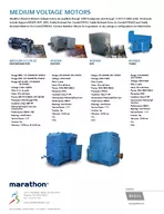
DC motors are configured in many types and sizes including brushless servo and gearmotor types A motor consists of a rotor and a permanent magnetic field stator The magnetic field is maintained using either permanent magnets or electromagnetic windings DC motors are most commonly used in ID: 526330

motor armature field motors armature motor motors field current torque speed coil series types windings magnetic shunt load power

Share:

Link:

Embed:

Download Presentation from below link

Download Presentation The PPT/PDF document "What are DC Motors?" is the property of its rightful owner. Permission is granted to download and print the materials on this web site for personal, non-commercial use only, and to display it on your personal computer provided you do not modify the materials and that you retain all copyright notices contained in the materials. By downloading content from our website, you accept the terms of this agreement.


Presentation Transcript

Slide1

What are DC Motors?

DC motors are configured in many types and sizes, including brushless, servo, and

gearmotor types. A motor consists of a rotor and a permanent magnetic field stator. The magnetic field is maintained using either permanent magnets or electromagnetic windings. DC motors are most commonly used in variable speed and torque applications.Brushed DC motors have built-in commutation, meaning that as the motor rotates, mechanical brushes automatically commutate coils on the rotor. Brushless DC motors use an external power drive to allow commutation of the coils on the stator. Brush-type motors are used when cost is a priority, while brushless motors are selected fulfill specific requirements, such as maintenance-free operation, high speeds, and hazardous environments where sparking could be dangerous.

Motion and controls covers a wide range of components that in some way are used to generate and/or control motion. Areas within this category include bearings and bushings, clutches and brakes, controls and drives, drive components, encoders and resolvers, Integrated motion control, limit switches, linear actuators, linear and rotary motion components, linear position sensing, motors (both AC and DC motors), orientation position sensing, pneumatics and pneumatic components, positioning stages, slides and guides, power transmission (mechanical), seals, slip rings, solenoids, springs.

Motors are the devices that provide the actual speed and torque in a drive system.  This family includes AC motor types (single and multiphase motors, universal, servo motors, induction, synchronous, and gear motor) and DC motors (brushless, servo motor, and gear motor) as well as linear, stepper and air motors, and motor contactors and starters.Slide2

D. C. Motor

Applications in rolling mills, traction, overhead cranesPrinciple of Operation

When a current carrying conductor is placed in a magnetic field, it experiences a mechanical force whose direction is given by Fleming’s left hand rule.Slide3

When the coil is powered, a magnetic field is generated around the armature. The left side of the armature is pushed away from the left magnet and drawn toward the right, causing rotation.

The armature continues to rotate

When the armature becomes horizontally aligned, the commutator

reverses the direction of current through the coil, reversing the magnetic field. The process then repeats. Slide4

CONTENT

PAGE

ACKNOWLEDGEMENTREPORT CONTENT - INTRODUCTION - DESCRIPTION SUMMARYREFERENCESSlide5

Constructionally, D.C. Generator and D.C. motor have no

basic difference

+ Armature carrying current downwards- Armature carrying current upwardsBack EMFWhen the motor armature rotates, the conductors cut the flux. So,according to laws of electromagnetic induction, EMF is induced

in them whose direction, according to Fleming’s Right Hand Rule is

in opposition to the applied voltage. So, it is referred to as

Back EMF

E

b

.

So, V has to drive

I

a

against

E

b

.Slide6

Acknowledgement

I would like to acknowledge and extend my heartfelt gratitude to the following persons who have made the completion of this

assignment possible: Our teacher,Ms Maslinda for her vital encouragement and support.

My

father

,Hamidon

Bin

Awang

for

his

understanding and assistance

.

Thanks for lending me your precious engineering book that consist the

collection of the topics for

this assignment.

My

brother,Helmi

Bin

Hamidon

for

the

constant reminders and much needed motivation.

My

mom,Azizah

Bte

Abd

Ghani

for

the

help,

inspiration

and love she

extended.

All

my batch

members in third semester

And

to Allah

, who made all things possible.Slide7

ACKNOWLEDGEMENTS

I would like to express the deepest appreciation to my committeechair, Professor Godfrey-Sykes Irvine, who has the attitude and

the substance of a genius: he continually and convincinglyconveyed a spirit of adventure in regard to research andscholarship, and an excitement in regard to teaching. Withouthis guidance and persistent help this dissertation would not havebeen possible.I would like to thank my committee members, Professor M.Chaphaga Tridactyla and Professor Marmaduke Orange, whosework demonstrated to me that concern for global affairssupported by an “engagement” in comparative literature andmodern technology should always transcend academia andprovide a quest for our times.In addition, a thank you to Professor V. Milicic of WesternUniversity, who introduced me to Linguistics, and whoseenthusiasm for the “underlying structures” had lasting effect.I thank the University of Chicago Press for permission to includecopyrighted photographs as part of my thesis/dissertation. I also

thank Springer

Verlag

for permission to include Chapter Five of

my dissertation, which was originally published in Linguistics

Journal. Financial support was provided by the University of

California, Irvine, NSF Grant DEB-8227052 and a MacArthur

predoctoral

fellowship in International Peace and Security

granted by the Social Science Research Council.Slide8

Neglecting Brush Drops (since small)

Voltage Equation of a Motor

VI

a

= Electrical Input to the armature

E

b

I

a

= Electrical Equivalent of Mechanical Power

developed in Armature

I

a

2

R

a

=Armature Copper LossSlide9

Armature Torque (Ta

)

If Ta be the torque developed by the armature of a motor running at N rpsPower developed = Electrical Power converted into Mechanical Power in the Armature= EbIa WattSlide10

Series Motor

Shunt MotorSlide11

Shaft Torque (T

sh)

Whole of Armature torque Ta is not available for useful work.A percentage of it is required for supplying iron and friction losses In the motor.Tsh is the shaft or useful torque.Ta-Tsh is the lost torque

Speed of a D.C. MotorSlide12

SUMMARY

This chapter presented the operating principles and characteristics of direct-current motors. The following information provides a summary of the main subjects for review.

The main PRINCIPLE OF A DC MOTOR is that current flow through the armature coil causes the armature to act as a magnet. The armature poles are attracted to field poles of opposite polarity, causing the armature to rotate. The CONSTRUCTION of a dc motor is almost identical to that of a dc generator, both physically and electrically. In fact, most dc generators can be made to act as dc motors, and vice versa. COMMUTATION IN A DC MOTOR is the process of reversing armature current at the moment when unlike poles of the armature and field are facing each other, thereby reversing the polarity of the armature field. Like poles of the armature and field then repel each other, causing armature rotation to continue.

COUNTER-ELECTROMOTIVE FORCE

is generated in a dc motor as armature coils cut the field flux. This

emf

opposes the applied voltage, and limits the flow of armature current.

In

SERIES MOTORS

, the field windings are connected in series with the armature coil. The field strength varies with changes in armature current. When its speed is reduced by a load, the series motor develops greater torque. Its starting torque is greater than other types of dc motors. Its speed varies widely between full-load and no-load. Unloaded operation of large machines is dangerous.

In

SHUNT MOTORS

, the field windings are connected in parallel (shunt) across the armature coil. The field strength is independent of the armature current. Shunt-motor speed varies only slightly with changes in load, and the starting torque is less than that of other types of dc motors.

In

COMPOUND MOTORS

, one set of field windings is connected in series with the armature, and one set is connected in parallel. The speed and torque characteristics are a combination of the desirable characteristics of both series and shunt motors.Slide13

LOAD

on a motor is the physical object to be moved by the motor. DC MOTOR ARMATURES

are of two types. They are the Gramme-ring and the drum-wound types. THE GRAMME-RING ARMATURE is inefficient since part of each armature coil is prevented from cutting flux lines. Gramme-ring wound armatures are seldom used for this reason. THE

DRUM-WOUND ARMATURE

consists of coils actually wound around the armature core so that all coil surfaces are exposed to the magnetic field. Nearly all dc motors have drum-wound armatures.

MOTOR REVERSAL

in a dc motor can be accomplished by reversing the field connections or by reversing the armature connections. If both are reversed, rotation will continue in the original direction.

SPEED CONTROL IN A DC MOTOR

is maintained by varying the resistance either in series with the field coil or in series with the armature coil. Increasing shunt-field circuit resistance increases motor speed. Increasing the armature circuit resistance decreases motor speed.

ARMATURE REACTION

is the distortion of the main field in a motor by the armature field. This causes the neutral plane to be shifted in the direction opposite to that of armature rotation.

Interpoles

and compensating windings are used to reduce the effect of armature reaction on motor operation.

STARTING RESISTORS

are necessary since the dc resistance of a motor armature is very low. Excessive current will flow when dc voltage is first applied unless current is limited in some way. Adding resistance in series with the armature windings reduces initial current. It may then be removed after counter

emf

has been built up. Slide14

references

Internet - thesaurusA text book of Electrical Technology

in S.I. units by B.L. Theraja