/
NICHICON CORPORATION General Descriptions of Aluminum NICHICON CORPORATION General Descriptions of Aluminum

NICHICON CORPORATION General Descriptions of Aluminum - PDF document

marina-yarberry
marina-yarberry . @marina-yarberry
Follow
384 views
Uploaded On 2015-06-07

NICHICON CORPORATION General Descriptions of Aluminum - PPT Presentation

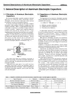
8101C An aluminum electrolytic capacitor consists of cathode aluminum foil capacitor paper electrolytic paper electrolyte and an aluminum oxide layer which acts as the dielectric formed on the anode foil surface A very thin oxide layer formed by elec ID: 82122

8101C aluminum electrolytic capacitor

Share:

Link:

Embed:

Download Presentation from below link

Download Pdf The PPT/PDF document "NICHICON CORPORATION General Description..." is the property of its rightful owner. Permission is granted to download and print the materials on this web site for personal, non-commercial use only, and to display it on your personal computer provided you do not modify the materials and that you retain all copyright notices contained in the materials. By downloading content from our website, you accept the terms of this agreement.


Presentation Transcript

NICHICON CORPORATION General Descriptions of Aluminum Electolytic Capacitors TECHNICAL NOTES CAT.8101C rectifying properties. When in contact with electrolyte, theinsulation property. Together with magnified effectivefoil (anode and cathode) with paper interleaved. This foilimpregnated with electrolyte. The construction of ancapacitor has polarity. If both the anode and cathode foilsimpregnated with liquid electrolyte. There is another type Fig. 1-1 1. General Description of Aluminum Electrolytic Capacitors "and the surface area "S" must be large while thethickness "d" must be small. Table 1-1 shows thecapacitors. Therefore, aluminum electrolytic capacitorsDC current. Fine surface etching (photo 1-1) 8.855 10 Type of CapacitorDielectricDielectric ConstantDielectric Thickness d ( Aluminum Electrolytic CapacitorAluminum Oxide7~10(0.0013~0.0015/V) Tantalum Electrolytic CapacitorTantalum Oxide24(0.001~0.0015/V) Film Capacitor (Metallized)Polyester Film3.20.5~2 Ceramic Capacitor (High Dielectric Constant Type)Barium Titanate500~20,0005Ceramic Capacitor (Temp. Compensation Type)Titanium Oxide15~2505 Table 1-1 Dielectric constants and minimum thickness of dielectrics used in various types of capacitorsCapacitance of Aluminum Electrolytic1-1 Principles of Aluminum ElectrolyticCapacitors e SurfaceSectionSection (Replica) cylindrical shape. This is called a "capacitor element." Atconnected. With the aluminum oxide layer formed on thehigh value of capacitance is now attainable. That is to saythat the electrolyte is now functioning as a cathode. The (3)It must be chemically stable with the anode andelectrolytic capacitors. For this reason, the properto form an aluminum oxide layer on its surface. Thisaluminum electrolytic capacitor. The DC voltage that ism/V).O[Al(OH FomeddielectricdielectricFomed20V Fomed ProcessMain MaterialsContents cathode foil are continuously etched electrochemically in a chloride solution with an AC or DC current. This enlarges the aluminum oxide film on the surface of the cathode foil. As for Fig. 1-2 Winding aftixingmaterialElementLeadElectrolyticpaperFoil ProsessMain MaterialsContents ElementImpregnationElectrolyteAssembly&FinishingAgingInspection ProcessingPackaging ShippingElementsElectrolyteImpregnated elementsCase (usually aluminum) Rubber packing, Rubber-bakelite with terminals ( Mold plastic with terminals )Exterior housing material(Sleeving, bottom plate, etc.)Assembled productsPlastic platformTaping material (Capacitor mounting braketPackaging materialsElements are impregnated with liquid electrolyte.The clearance between the two electrode foils is filled with liquid electrolyte. With this impregnation, an element can function as a capacitor.The impregnated element, case and end seal are assmbled. For the end seal , a rubber packing, a rubber lined bakelite (with terminals) or a molded plastic plate (with terminals) are After assembly, the capacitors are covered with exterior housing material. Sleeving is not used for laminate case products, such as surface mount capacitors.DC voltage is applied under high temperature conditions to reform the oxide film.Leads are processed and the plastic platform is attached to surface mount capacitors.Depending on customer specification, the lead cutting, forming, snap - in and taping are processed.An inspection based on the standard specification and test requirements is performed to guarantee the quality of � �� ������������������� �� ������������������� �� ������������������� �� ������������������� �� ������������������� ���������������������� �������� ������ ������� Fig. 1-3Fig. 1-4 ������������� Fig. 1-5 Nylon laminate casing for laminate products (sleeveless)(may or may not be - used) NICHICON CORPORATION General Descriptions of Aluminum Electolytic Capacitors TECHNICAL NOTES CAT.8101C 1-6 Characteristics1-6-1 Capacitance as a dielectric. According to the construction of aluminumseries. Therefore, the capacitance can be determined byThe standard capacitance tolerance is 20%(M); 1-6-2 Equivalent Series Resistance (R), Dissipation (50Hz~1kHz) and can be regarded as zero. Therefore, Fig. 1-7 1 RR(1 - 2)(1 - 3)(1 - 4)(1 - 5)R ( ) wC tand Fig. 1-6 C Capacitance (F)R Equivalent series resistance (L Equivalent series inductance (H) = Ca Cc = 8.855 10(mF)eSd temperature for a specified time period. When selecting a 210-310-210-1110103104105106RXcXLZFrequency (Hz) R (W), Z(W) Fig. 1-8 L -- wC1 Z =+ j jwC1 types of capacitors. The following section explains thethe temperature decreases. The relationship betweenimpedance changes with temperature and frequency. An -60-40-20020406080100120 Fig. 1-9 Capacitance vs. Temperature Characteristics mF 105oC Z -60-40-20020406080100120 mF 105oC Z 1001k10k100k1001k10k100kFig. 1-11 Impedance, ESR vs. Frequency Characteristics oC+20oC ESR-25oC+20oC+65oC+105oC mF 105oC200V 470mF 105oC Fig. 1-10 Tan Characteristics 25oC oC+65oC+105oC mF 105oC1000.010.11101k10kFrequency (Hz) mF 105oC oC+20oC+65oC+105oC 4060-200801001204060-20080100120 Fig. 1-12 Leakage current vs. Temperature Characteristic mF 105oC200V 470mF 105oCMeasured after 1 minuteapplication of rated voltageMeasured after 5 minutesapplication of rated voltage NICHICON CORPORATION TECHNICAL NOTES CAT.8101C NICHICON CORPORATION TECHNICAL NOTES CAT.8101C