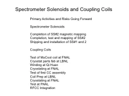
Primary Activities and Risks Going Forward Spectrometer Solenoids Completion of SS2 magnetic mapping Completion test and mapping of SS2 Shipping and installation of SS1 and 2 Coupling Coils ID: 591540
Download Presentation The PPT/PDF document "Spectrometer Solenoids and Coupling Coil..." is the property of its rightful owner. Permission is granted to download and print the materials on this web site for personal, non-commercial use only, and to display it on your personal computer provided you do not modify the materials and that you retain all copyright notices contained in the materials. By downloading content from our website, you accept the terms of this agreement.
Slide1
Spectrometer Solenoids and Coupling Coils
Primary Activities and Risks Going Forward
Spectrometer Solenoids
Completion of SS#2 magnetic mapping
Completion, test and mapping of SS#2
Shipping and installation of SS#1 and 2
Coupling Coils
Test of
MuCool
coil at FNAL
Cryostat parts fab at LBNL
Winding at Qi
Huan
Cryostating
at FNAL
Test of first CC assembly
Coil Prep at LBNL
Cryostating
at FNAL
Test at FNAL
RFCC IntegrationSlide2
Spectrometer Solenoid Update
Steve
Gourlay
For Steve
Virostek
Lawrence Berkeley National LabSlide3
Topics
Latest
magnet training results
Summary of 2nd magnet progress
Control system upgrade
Risks
and mitigationSlide4
MICE Cooling Channel Layout
Spectrometer Solenoid #1
Spectrometer Solenoid #2Slide5
Current
Progress (1
st
magnet)
The first magnet (designated SS#2) has been successfully trained to full flip and solenoid mode currents
Current was maintained at full flip mode for a period of 24 hours with no quench
All five power supplies were used at various ramp rates and under computer control
Numerous improvements and fixes implemented on control and power supply systems
Improved cold mass heater control loop worked well
Cold mass is being held at 4K and full of
LHe
in preparation for upcoming 3D magnetic mappingSlide6
Working on Both Magnets
Assembly
Training
completeSlide7
Recent Training Runs
HTS lead failure
After warmup, HTS lead replace and cooldown
After
warmup
, control sys
mods
, and
cooldown
Vent line
blockage
Target training current achieved (283 A)Slide8
Final Training ProgressionSlide9
2nd Magnet Progress
The
cold
mass/shield assembly is
complete, MLI wrapped and suspended in
the vacuum
vessel
Installation
of the
cryocooler
tower
is
complete
First stage cooler connections to the thermal shield are being installed
Vacuum vessel end plates are now being welded
LBNL mechanical technicians playing a key role in
assembly (instrumentation, MLI wrap, HTS leads)Slide10
2
nd
Magnet ProgressSlide11
Control
System
Upgrade
A control system review was held at LBNL on December 11
th
and 12
th
, 2012
The LBNL/MICE team
developed improvements from the
numerous
review panel recommendations
The
current system is more
robust
and capable
of
protecting the magnet from potential
failures
A secondary goal
of the upgrade was
to move closer to the final system
to
be operated in the MICE hallSlide12
Control
System
Upgrade
Several
of the
primary upgrades
:
Stand
alone PID controller for the cold mass heater circuit
with current
monitor
Alarm
handler to the control software
Gas
bottle backup
system prevents
negative cold mass
pressure;
improved durability of
PRV’s
New current shunts
directly measure the current
in each coilSlide13
Power Supplies and Control
Power Supplies
New 500 A supply for center and end coils
5 supplies fully integrated
System verified during recent training runs
Control rack
Many upgrades installed
New
heater control
loop
UPS addedSlide14
Upcoming Tasks
3D magnetic bore mapping of first unit using CERN developed system to begin later in May with iron shielding disk in place
Second
unit assembly
to
be
completed
in
next two to three weeks
After vacuum
pumpout
of 2
nd
magnet,
cooldown
and training to start in June
Shipping of fully commissioned magnets to RAL planned for July and SeptemberSlide15
Risks and Mitigation
SS controls operational readiness
certification
Lack of a complete, fully operational and integrated control system led to previous system failures
Some risk remains as the final system to be implemented at RAL is still being developed
Mitigation: numerous upgrades have been implemented and testing during SS#2 training; additional improvements are under way, and the system will be tested during SS#2 mapping and SS#1 training/mappingSlide16
Risks and Mitigation (cont’d)
SS#2 re-train and re-test
Addition of the iron shield for mapping will alter the coil forces and possibly lead to the need for some re-training
Magnet has always required re-training after warm-up and subsequent cool-down
Mitigation:
The cold mass has been maintained at 4K since the completion of the training runs, avoiding any re-training due to thermal expansion/contraction
The forces due to the shield are only a fraction of the nominal inter-coil forces
The training procedure is well establishedSlide17
Risks and Mitigation (cont’d)
SS#2 operational failure with iron shield
Some risk presented as iron shield has never been fitted to the vacuum vessel, and magnet has never been operated with the shield in place
Mitigation:
Iron shield supports designed with conservative safety factors and adequate adjustment capability; fast turnaround modifications possible using Wang NMR and/or LBNL shop
Magnetic forces on cold mass supports are only a fraction of the calculated loads present during operation with other MICE magnets in place; cold mass supports designed and load tested 10% beyond operational requirementsSlide18
Risks and Mitigation (cont’d)
SS#1 train and test
SS#1 represents a newly modified and assembled system that has never been tested in this configuration
Risk areas include: coil windings, cold leads, HTS lead connections, heat leaks, other mechanical systems
Mitigation:
The SS#1 cold mass has been previously trained to ~200 A
The design and as-built configuration of SS#1 is identical to that of SS#2
The same technician crew that assembled SS#2 is also working on completing SS#1Slide19
Risks and Mitigation (cont’d)
SS#1 operational failure with iron shield
The risks and mitigation are the same as those for SS#2
All training and testing of SS#1 will likely be carried out with the shield in placeSlide20
Coupling Coils
Steve
Gourlay
For
Allan
DeMelloSlide21
Coupling Coil Sub-assembliesSlide22
Coupling
Coil Cold Mass
Winding of cold mass coils #2, #3 and #4 by
QiHuan
Company (Beijing, China)
Preparation cold mass coils #2, #3 and #4 at LBNL
Magnetic test of cold mass coils #2, #3 and #4 at FNAL
Risks to schedule
Delay getting superconductor to China
Problem with winding process at
QiHuan
Leak in cooling pipe after pressure test at LBNL
Damage during shipping to FNAL
Problem during magnetic testingSlide23
Coupling
Coil Cryostat
Single Cavity Vacuum Vessel Exploded View
LBNL mechanical shop is in the process of fabricating the first cryostat
Estimated completion on 7-1-2013
Drawings will be updated to reflect the “as built” cryostat
Determine fabricator for the additional 2 cryostats
Risks to schedule
Delay in fabrication process
Vessel not vacuum tight
Damage during shipping to FNALSlide24
Coupling Coil Thermal Shield
Thermal shield design is nearly complete
Drawings
have been red lined but not updated
Some
SINAP parts/drawings will need to be revised for better
manufacturability
LBNL shops will
fabricate
the first thermal shield
Risks to schedule
Delay getting drawings finished
Problem with fabrication process
Damage during shipping to FNALSlide25
Cold Mass Fully Assembled (at FNAL)
Reservoir/cooling circuit installation complete
Cold mass support brackets and band installed
Cold mass wrapped with MLI
Risks to schedule
Delay getting bands fabricated
Leak in reservoir circuitSlide26
Cooling
Circuit
Finalize cooling circuit design
Create detail fabrication drawings
Fabrication of component parts
Assemble components
Risks to schedule
Delay fabrication of component parts
Unforeseen problem during assemblySlide27
CCM Prototype Assembly at FNAL
Cold mass prepared for integration with cryostat
Mount cold mass support bracket and bands
Wrap cold mass in MLI
Assemble thermal shield around cold mass
Wrap assembly in MLI
Insert cold mass into cryostat
Attach cold mass support bands to cryostat
Align magnet in the cryostat
Weld on cryostat tower and inner bore
Risks to schedule
Unforeseen problem during assembly
Vessel not vacuum tightSlide28
CCM Prototype Assembly at FNAL
Weld tower assembly to cryostat
Assemble upper cooling circuit
Attach upper cooling circuit to the cold mass cooling circuit
Risks to schedule
Unforeseen problem during assembly
Cooling circuit leak due to welding error
Vacuum leak in cryostatSlide29
CCM Prototype Assembly at FNAL
Add
cryocoolers
to cooling circuit
Coupling coil training and testing
Risks to schedule
Magnet does not get to cold enough for superconducting operation with
cryocoolers