/
Analog Applications Journal Texas Instruments Incorporated HighPerformance Analog Products Analog Applications Journal Texas Instruments Incorporated HighPerformance Analog Products

Analog Applications Journal Texas Instruments Incorporated HighPerformance Analog Products - PDF document

min-jolicoeur
min-jolicoeur . @min-jolicoeur
Follow
556 views
Uploaded On 2014-12-13

Analog Applications Journal Texas Instruments Incorporated HighPerformance Analog Products - PPT Presentation

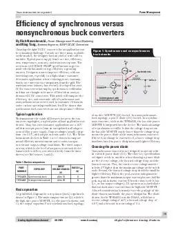
ticomaa 3Q 2010 Power Management Coupled inductors broaden DCDC converter usage Introduction Recently inductor manufacturers have begun to release offtheshelf coupled inductors Consisting of two separate inductors wound on the same core coupled induc ID: 23388

ticomaa 2010 Power Management

Share:

Link:

Embed:

Download Presentation from below link

Download Pdf The PPT/PDF document "Analog Applications Journal Texas Instru..." is the property of its rightful owner. Permission is granted to download and print the materials on this web site for personal, non-commercial use only, and to display it on your personal computer provided you do not modify the materials and that you retain all copyright notices contained in the materials. By downloading content from our website, you accept the terms of this agreement.


Presentation Transcript

10 Analog Applications JournalTexas Instruments Incorporated High-Performance Analog Products www.ti.com/aa 3Q 2010 Power ManagementCoupled inductors broaden DC/DC converter usageRecently, inductor manufacturers have begun to release off-the-shelf coupled inductors. Consisting of two separate inductors wound on the same core, coupled inductors typically come in a package with the same length and width as that of a single inductor of the same inductance value, only slightly taller. The price of a coupled inductor is also typically much less than the price of two single inductors. turns—ipep.0L0turnsratio—butsomeneweroneshave higher turns ratio. The coupling coefficient, K, of coupled inductorsistypicallyaround customtransformer1scoefficientofgreaterthan7p88pThe mutual inductance of coupled inductors makes them perform somewhat inefficiently in flyback applications and inductor waveforms. Also, the current specifications for a coupled inductor are different depending on whether its windings are physically connected in series or in parallel. For example, when the windings are connected in series, andRsScurrentratingsmustbeappliedtothecurrent flowing simultaneously through both windings, unless wise stated in the data sheet. With this understand ing of the specifications, some examples of coupled inductors in real applications can now be examined.While not new, the DC/DC single-ended primary induc controller can be configured as a SEPIC, but this was rarely used until recently. Two factors have contributed to theS:rGS1snewfoundpopularityL00µGSmanufacturers have begun making more boost controllers with current- manufacturers have begun making single-packaged coupled inductors that minimize the converter’s overall PCB footprint. Specifically, the power-supply footprint of many applications with two separate inductors can be reduced by a third when a coupled inductor is used instead. Figure 1 Texas and the Wuerth 744877220.By Jeff FalinSenior Applications Engineer TWH3((µ4 Figure 1. SEPIC using the TI TPS61170 and Wuerth 744877220 Texas Instruments Incorporated 11 Analog Applications Journal 3Q 2010 www.ti.com/aa High-Performance Analog Products Power ManagementEven more appealing, using a SEPIC with a 1:1 coupled inductor forces the inductor ripple current to split between the two windings, allowing the use of half the inductance that two single inductors would require for the same ripple current. Compared to two single inductors at twice the inductance value in a package of the same size, the coupled inductor has lower DC resistance, which helps increase overall converter efficiency. Specifically, with a 15-V input and a 12-V, 325-mA output, the SEPIC in efficiencyp more information.ZETA converter with smaller footprintA ZETA converter provides the same buck and boost functionality as a SEPIC by using two inductors and a coupling capacitor, but with a buck controller instead of a boost controller. Figure 2 shows the TI TPS40200 and the Coiltronics DRQ74 in a ZETA configuration. Benefiting 1pp aR5 Figure 2. ZETA converter with TI TPS40200 and Coiltronics DRQ74from the split-inductor ripple current like the SEPIC, this ZETA converter requires half the inductance for the same ripple current. Also like the SEPIC, its overall power-supply footprint is a third smaller than with two separate inductors. Since the output inductor current flows continuously to the output in a ZETA converter, the ZETA converter’s output voltage has lower ripple than that of a SEPIC with the same inductance. Therefore, the ZETA may be a better fit for low-noise applications than a SEPIC. See Reference 2for more information. satchingpositiveandnegativepowerrailsarecommon requirements in industrial applications, especially for amplifiers. A wide-input-range buck converter can be configured to provide a negative output voltage. Replacing the inductor of this inverting buck converter with a coupled inductor and adding a diode and capacitor turns this Texas Instruments Incorporated 12 Analog Applications Journal High-Performance Analog Products www.ti.com/aa 3Q 2010 Power Managementinverting buck converter into one with a dual output. Figure 3 shows the TI TPS54160 and the Coilcraft 150-µH MSD1260 used in this fashion. Even though the difference between each rail is regulated instead of each rail being individually regulated, as long as the loads on each rail are somewhat close together, the coupled inductor assists in providing excellent regulation of each rail. See Reference 3 for more information.The output voltage of a DC/DC converter with integrated FETs is limited by the converter’s switch current rating. Tying a coupled inductor with a turns ratio greater than 1:1 to the converter’s switch (SW) pin can extend the effective output-voltage range of any boost converter. For example, Figure 4 shows the TI TPS61040 boost converter with a 30-V absolute maximum current rating configured to provide 35 V or more, and the Coilcraft LPR4012-103B, which is a 1:2 coupled inductor. When the coupled inductor is configured with the multiple-winding side in series with the diode, the single wound inductor—and therefore the converter’s switch FET—has only a third of the output voltage, minus the input voltage, across it.Most inductor manufacturers have a family of coupled inductors with a turns ratio of 1:1 or higher. So, think out of the box! Coupled inductors may expand the application space for a favorite DC/DC converter IC.For more information related to this article, you can download an Acrobat file at www.ti.com/lit/and replace “” with the TI Lit. # for the materials listed below. Document TitleTI Lit. # 1.Jeff Falin, “Designing DC/DC converters based on SEPIC topology,” Analog Applications Journal (4Q 2008) ........... slyt309 2.Jeff Falin, “Designing DC/DC converters based on ZETA topology,” Analog Applications (2Q 2010) ....................... slyt372 David G. Daniels, “Creating a split-rail power supply with a wide input voltage buck regulator,” Application Report .............. slva369 RT/CLK (+12 V at 0.3A)(–12 V at 0.3A) Figure 3. Split-rail buck converter using the TI TPS54160 and Coilcraft MSD1260 Related Web sitespower.ti.comwww.ti.com/sc/device/ with TPS40200, TPS54160, TPS61040, or TPS61170 © 2010 Texas Instruments Incorporated E2E is a trademark of Texas Instruments. All other trademarks are the property of SLYT TI Worldwide Technical Support Internet Home PageTI E2E™ Community Home Page Phone+1(972) 644-5580 Brazil Phone0800-891-2616 Mexico Phone0800-670-7544 Fax+1(972) 927-6377 Internet/Email Europe, Middle East, and Africa European Free Call00800-ASK-TEXAS International+49 (0) 8161 80 2121 Russian Support+7 (4) 95 98 10 701 The European Free Call (Toll Free) number is not active in all countries. If you have technical difficulty calling the free call number, please use the international number above. Fax+(49) (0) 8161 80 2045 Internet support.ti.com/sc/pic/euro.htJapan PhoneDomestic0120-92-3326 FaxInternational+81-3-3344-5317 Domestic0120-81-0036 Internet/EmailInternational support.ti.com/sc/pic/japan.ht Domestic www.tij.co.jp/pi Asia Phone International+91-80-41381665 Domestic Toll-Free Number Taiwan Fax+886-2-2378-6808 Internet The products and services of Texas Instruments Incorporated and its subsidiaries described herein are sold subject to TI’s standard terms and conditions of sale. Customers are advised to obtain the most current and complete information about TI products and services before placing orders. TI assumes no liability for applications assistance, customer’s applications or product designs, software performance, or infringement of patents. The publication of information regarding any other company’s products or services does not constitute TI’s approval, warranty IMPORTANTNOTICETexasInstrumentsIncorporatedanditssubsidiaries(TI)reservetherighttomakecorrections,modifications,enhancements,improvements,andotherchangestoitsproductsandservicesatanytimeandtodiscontinueanyproductorservicewithoutnotice.Customersshouldobtainthelatestrelevantinformationbeforeplacingordersandshouldverifythatsuchinformationiscurrentandcomplete.AllproductsaresoldsubjecttoTI’stermsandconditionsofsalesuppliedatthetimeoforderacknowledgment.TIwarrantsperformanceofitshardwareproductstothespecificationsapplicableatthetimeofsaleinaccordancewithTI’sstandardwarranty.TestingandotherqualitycontroltechniquesareusedtotheextentTIdeemsnecessarytosupportthiswarranty.Exceptwheremandatedbygovernmentrequirements,testingofallparametersofeachproductisnotnecessarilyperformed.TIassumesnoliabilityforapplicationsassistanceorcustomerproductdesign.CustomersareresponsiblefortheirproductsandapplicationsusingTIcomponents.Tominimizetherisksassociatedwithcustomerproductsandapplications,customersshouldprovideadequatedesignandoperatingsafeguards.TIdoesnotwarrantorrepresentthatanylicense,eitherexpressorimplied,isgrantedunderanyTIpatentright,copyright,maskworkright,orotherTIintellectualpropertyrightrelatingtoanycombination,machine,orprocessinwhichTIproductsorservicesareused.InformationpublishedbyTIregardingthird-partyproductsorservicesdoesnotconstitutealicensefromTItousesuchproductsorservicesorawarrantyorendorsementthereof.Useofsuchinformationmayrequirealicensefromathirdpartyunderthepatentsorotherintellectualpropertyofthethirdparty,oralicensefromTIunderthepatentsorotherintellectualpropertyofTI.ReproductionofTIinformationinTIdatabooksordatasheetsispermissibleonlyifreproductioniswithoutalterationandisaccompaniedbyallassociatedwarranties,conditions,limitations,andnotices.Reproductionofthisinformationwithalterationisanunfairanddeceptivebusinesspractice.TIisnotresponsibleorliableforsuchaltereddocumentation.InformationofthirdpartiesmaybesubjecttoadditionalResaleofTIproductsorserviceswithstatementsdifferentfromorbeyondtheparametersstatedbyTIforthatproductorservicevoidsallexpressandanyimpliedwarrantiesfortheassociatedTIproductorserviceandisanunfairanddeceptivebusinesspractice.TIisnotresponsibleorliableforanysuchstatements.TIproductsarenotauthorizedforuseinsafety-criticalapplications(suchaslifesupport)whereafailureoftheTIproductwouldreasonablybeexpectedtocauseseverepersonalinjuryordeath,unlessofficersofthepartieshaveexecutedanagreementspecificallygoverningsuchuse.Buyersrepresentthattheyhaveallnecessaryexpertiseinthesafetyandregulatoryramificationsoftheirapplications,andacknowledgeandagreethattheyaresolelyresponsibleforalllegal,regulatoryandsafety-relatedrequirementsconcerningtheirproductsandanyuseofTIproductsinsuchsafety-criticalapplications,notwithstandinganyapplications-relatedinformationorsupportthatmaybeprovidedbyTI.Further,BuyersmustfullyindemnifyTIanditsrepresentativesagainstanydamagesarisingoutoftheuseofTIproductsinsuchsafety-criticalapplications.TIproductsareneitherdesignednorintendedforuseinmilitary/aerospaceapplicationsorenvironmentsunlesstheTIproductsarespecificallydesignatedbyTIasmilitary-gradeor"enhancedplastic."OnlyproductsdesignatedbyTIasmilitary-grademeetmilitaryspecifications.BuyersacknowledgeandagreethatanysuchuseofTIproductswhichTIhasnotdesignatedasmilitary-gradeissolelyattheBuyer'srisk,andthattheyaresolelyresponsibleforcompliancewithalllegalandregulatoryrequirementsinconnectionwithsuchuse.TIproductsareneitherdesignednorintendedforuseinautomotiveapplicationsorenvironmentsunlessthespecificTIproductsaredesignatedbyTIascompliantwithISO/TS16949requirements.Buyersacknowledgeandagreethat,iftheyuseanynon-designatedproductsinautomotiveapplications,TIwillnotberesponsibleforanyfailuretomeetsuchrequirements.FollowingareURLswhereyoucanobtaininformationonotherTexasInstrumentsproductsandapplicationsolutions: Audiowww.ti.com/audio DataConverters Automotivewww.ti.com/automotive DLP®Products Communicationsand TelecomDSPdsp.ti.com Computersand ClocksandTimers ConsumerElectronics Interfaceinterface.ti.com Energywww.ti.com/energy Logiclogic.ti.com Industrialwww.ti.com/industrial PowerMgmt Medicalwww.ti.com/medical Microcontrollersmicrocontroller.ti.com Securitywww.ti.com/security RFIDwww.ti-rfid.com Space,Avionics& RF/IFandZigBee®Solutions VideoandImaging Wirelesswww.ti.com/wireless-apps MailingAddress:TexasInstruments,PostOfficeBox655303,Dallas,Texas75265Copyright©2010,TexasInstrumentsIncorporated