/
Analog Applications Journal Texas Instruments Incorporated Q  www Analog Applications Journal Texas Instruments Incorporated Q  www

Analog Applications Journal Texas Instruments Incorporated Q www - PDF document

mitsue-stanley
mitsue-stanley . @mitsue-stanley
Follow
468 views
Uploaded On 2014-12-16

Analog Applications Journal Texas Instruments Incorporated Q www - PPT Presentation

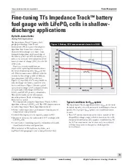
ticomaa HighPerformance Analog Products Power Management Finetuning TIs Impedance Track battery fuel gauge with LiFePO cells in shallow discharge applications The Impedance Track batteryfuel gauging technology from Texas Instruments TI is a powerful ID: 24889

ticomaa HighPerformance Analog Products Power

Share:

Link:

Embed:

Download Presentation from below link

Download Pdf The PPT/PDF document "Analog Applications Journal Texas Instru..." is the property of its rightful owner. Permission is granted to download and print the materials on this web site for personal, non-commercial use only, and to display it on your personal computer provided you do not modify the materials and that you retain all copyright notices contained in the materials. By downloading content from our website, you accept the terms of this agreement.


Presentation Transcript

13 Analog Applications Journal Texas Instruments Incorporated 1Q 2011 www.ti.com/aa j High-Performance Analog Products Power Management Fine-tuning TI’s Impedance Track ™ battery fuel gauge with LiFePO 4 cells in shallow- discharge applications The Impedance Track™ battery-fuel- gauging technology from Texas Instruments (TI) is a powerful adaptive algorithm that learns how a battery’s characteristics change over time. Com ing this algorithm with knowledge of the battery pack’s specific chemistry per - mits a very accurate determination of the battery’s state of charge (SOC) for the life of the pack. However, certain conditions are required for updating information about the total chemical capacity (Q max ) of the cell. This becomes more difficult with the extremely flat voltage profile of lithium- iron-phosphate (LiFePO 4 ) cells (see Figure 1), especially if it is not possible to fully discharge the battery and let it rest for several hours. Figure 1 shows typical open-circuit voltage (OCV) characteristics (DOD) LiCoO 2 and LiFePO 4 battery chemistries. This article builds on the discussions about Impedance Track technology in References 1 and 2. TI recommends using the Impedance Track 3 (IT3) algorithm with any LiFePO 4 cell. The IT3’s improvements to earlier Impedance Track algorithms include: • Bettercold-temperatureperformancefromimproved temperature compensation • Added • ImprovedaccuracyforunfavorableOCVreadingswith LiFePO 4 cells • Conservative - tional load-selection configurations IT3 is included in TI’s bq20z4x, bq20z6x, and bq27541-V200 gas gauges (not a comprehensive list). By Keith James Keller Analog Field Applications Figure 1. Battery OCV measurements based on DOD Typical conditions for Q max update The Impedance Track algorithm defines Q max as the total chemical capacity of a cell, measured in milliampere-hours (mAh). For a proper Q max update, two conditions must be met: 1.Two OCV measurements must be taken outside of the disqualified voltage range, which is based on the cell’s An OCV measurement can be done only on a relaxed cell that has not been charged or discharged for several hours. Texas Instruments Incorporated 14 Analog Applications Journal High-Performance Analog Products www.ti.com/aa j 1Q 2011 Power Management Reference 3 lists a subset of the disqualified voltage ranges, some of which are shown in Table 1. It can no OCV measurements are allowed if any cell voltages are above 3737mVorbelow3800mV.Thisis essentially a “keep out” range for OCV measurements for best accu racy. Even though an SOC percent - age is given in this article, the gauge determines disqualification based only on voltage. 2.A minimum amount of passed charge must be integrated by the fuel gauge. By default, it is set at 37%ofthetotalcellcapacity.This percentage of passed charge can be decreasedtoaslowas10%for shallow-discharge Q max update. This decrease will be at the expense of SOC accuracy but will be tolera - ble in a system that would not wise be able to update Q max . Now that we have an understanding of what is required for a shallow- discharge Q max update, let’s look at an example of data-flash parameters that need to be changed in a configuration with a lower-capacity pack. The default Impedance Track algorithm is based on typical laptop battery packs having 2 parallel strings of 3 cells in series (3s2p). Each string has a 2200-mAh capacity, giving a total capacity of 4400 mAh. LiFePO 4 cells have approx - imately half of that capacity, so if they are used in a 3s1p configuration, the total pack capacity will be 1100 mAh. With smaller-capacity packs like this, specific data-flash parameters need to be fine-tuned in TI’s gas-gauge evaluation software for optimal performance. The remainder of this article describes this process. Example calculations Consider a 3s1p-configuration battery pack using A123 4 /carbon cells. TI’s chemicalIDnumberforthiscelltypeis404.Thisbattery will be used in a storage system with normal temperatures of around 50°C. The discharge rate is 1C, and a 5-m sense resistor is used with the gauge for coulomb counting. As can be seen in Table 1, the disqualified voltage range 4 cells have a very wide disqualified However, depending on the cell characteristics, it may be possible to identify a higher minimum disqualified voltage for a shallow-discharge Q max it is possible to raise this value to 3322 mV, allowing for a shallow Q max -updatewindowfrom3309to3322mV(see Figure 2). The designer can use this midrange low-error window with data-flash modifications. Since only a high and low disqualified voltage range can be programmed, the host system must guarantee that the lower OCV mea - mV. - tion error increases, OCV-measurement error increases dramaticallybetween3274and3309mV.)Eventhough there is only a 13-mV window to work with for the lower - LiFePO 4 cells have a very long relaxation time, so let’s increase the data-flash parameter “OCV Wait Time” to battery’s Table 1.Excerpt from Reference 3 showing disqualified voltage ranges based on chemistry for Q max update Description Chemical ID Vqdis_min (mV) Vqdis_max (mV) SOC_min, % SOC_max, % LiCoO2/graphitized car - bon (default) 100 3737 3800 26 54 Mixed Co/Ni/Mn cathode 101 3749 3796 28 51 Mixed Co/Mn cathode 102 3672 3696 6 14 LiCoO2/carbon 2 103 3737 3800 26 54 Mixed Co/Mn cathode 2 104 4031 4062 77 88 LiFePO4/carbon 404 3274 3351 34 93 LiFePO4/carbon 409 3193 3329 12 92 02040SOC(%)6080100 43.532.521.510.50–0.5–1SOC Error(%) Midrange Window withLower Correlation Error 3274 mV 3322 mV 3351 mV 3309 mV Region Usedfor Shallow-DischargeQUpdatemax “Keep Out”Region forVoltage Measurement LiFePO4(ID 404)LiCoO2 Figure 2. SOC correlation error for 1-mV voltage error Texas Instruments Incorporated 15 Analog Applications Journal 1Q 2011 www.ti.com/aa j High-Performance Analog Products Power Management operating temperature is elevated, the parameter “Q Temperature” Additionally, “Q max Time” 21,600 seconds (6 hours). To decrease the Q max the“DODMaxCapacityError,”“MaxCapacityError,”and “Q max Filter” need to be modified, as they all play a part in the disqualification time between the OCV1 and OCV2 measurements. “Q max Filter” is a compensation factor that varies Q max relative to passed charge. “MaxCapacityError”basedonmeasuredpassedcharge However, these values need to be changed to allow for the shallow-discharge Q max update. Example 1: Time-out period for Q max update To set by the hardware to a fixed value of 10 µV, the time-out period for the Q max update can be determined as follows: 10 µV/10 m error. 10-mAh capacity error/1-mA offset current Therefore, from start to finish, including rest periods, only 10 hours are available to complete a Q max update. After the 10-hour time-out, once the gauge takes its next proper OCV reading, this timer will restart. Example 2: Modifying data-flash parameters In the design scenario using 1100-mAh cells with a 5-m sense resistor, the time-out period for the Q max update is determined in the same way: 10 µV/5 m In this case, the percentage of capacity error needs to be relaxed to increase the Q max time-out.Changingthe“Max which will increase the Q max disqualification time to The“DODCapacityError”needstobesettotwicethe “MaxCapacityError,”solet’schangeitto6%(fromthe max Filter” needs to be decreased proportionally, based on the percentage of passed charge: “Q max Table 2 shows typical data-flash parameters in gas- gauge evaluation software that must be modified to imple - ment a shallow-discharge Q max update. These particular parameters are protected (classified as “hidden”) but can be unlocked by TI’s applications staff. The example bat - tery pack used for this table is the one mentioned earlier, Table 2.Protected data-flash parameters that can be changed by TI applications staff based on system usage DATA-FLASH PARAMETER DEFAULT VALUE NEW VALUE Min % Passed Charge for Q max 37% 10% Min % Passed Charge for 1st Q max 90% Keep default at 90% 1 Q Invalid MaxV 3351 mV (chemical ID 404 default) Keep chemical ID 404 default at 3351 mV Q Invalid MinV 3274 mV (chemical ID 404 default) 3322 mV OCV Wait Time 1800 seconds 18,000 seconds DOD Capacity Err 2% 6% Q max Max Time 18,000 seconds 21,600 seconds Max Capacity Error 1 3 Q max Filter 96 26 Q Invalid MaxT 40 55 Q Invalid MinT 10 Keep default at 10 2 1 This parameter is important during the golden-image process If a standard 42-V Li-ion cell is being used and charged only to 41 V in- system, it is still necessary for the first Q max update to occur after the cell is charged to 42 V to meet the requirement for a 90% change in The capacity change is checked against both the specified cell capacity, or “Design Capacity,” and the estimated DOD for the start and end points based on the chemical ID number programmed in the gauge 2 A wide-ranging temperature change can cause errors when Q max is calculated In a system with normal operation at high or low temper - atures, it is necessary to modify this parameter Texas Instruments Incorporated Analog Applications Journal High-Performance Analog Productswww.ti.com/aaj1Q 2011Power Management/carbon The following events describe a practical approach to achieving a Q update after the data-flash parameters described in Examples 1 and 2 have been changed.A Q update should start when the battery voltages are within the low-correlation-error window as shown in Figure 2. The designer’s own algorithm can be used to discharge/charge the cells into this range.*2.In this example, to be in the valid measurement range 3322 mV. If cell voltages happen to relax outside the valid range during the discharge routine, another discharge or charge cycle must be started prior to the proWaitTime”voltagesarewithin3309to3322mVafterhoursand10 minutes, a proper OCV measurement has been taken.3.The next step is to fully charge the battery. Once the 6 hours and 10 minutes before the second OCV measurement is taken. The Q value will then be updated. If charging takes approximately 2 hours, then a miniFrom the calculation of the 16.5-hour time-out period in Example 2, we know there is more than enough time 4.The OCV timer can always be reset by issuing the gas gauge a ResetCommand (0x41) while the gauge is in unsealed mode.Table 3 shows the results from cycling the battery as just described when the example pack configuration is used.TI’s Impedance Track technology is a very accurate algorithm for determining battery SOC over the life of the cell. In LiFePO applications where a full discharge of the battery with a rest period is not possible, it is necessary to explore a shallow-discharge option for the Q update. This article has described the considerations and data-flash programming configurations for implementing a shallow-discharge Q update. Changes to these parameters must be approved by TI applications staff based on system configuration and requirements.For more information related to this article, you can download an Acrobat Reader file at www.ti.com/lit/and replace “” with the TI Lit. # for the materials listed below.Document TitleTI Lit. #1.“Theory and implementation of Impedance Track™ battery fuel-gauging algorithm in bq20zxx product family,” Application ReportKeith James Keller, “Fuel-gauging considera-tions in battery backup storage systems,” Analog Applications Journal (1Q 2010) ....table.xls [Online]. Available: http://www.ti.com/Related Web sitespower.ti.comwww.ti.com/sc/device/ with BQ20Z40-R1 or BQ27541-V200Table 3. Results from full-cycle and shallow-charge Q updates UPDATED QUPDATED QRESTING VOLTAGE Cell 01062Cell 11066Cell 21064Charging from empty after rest to full charge with rest *Because of the long voltage hysteresis of LiFePO cells after charge or discharge, it is preferable to discharge the battery only into the shallow- discharge range. It is okay to charge the battery during the hone-in algorithm Voltage” at any time. It is also permissible to have multiple discharges to get © 2011 Texas Instruments IncorporatedE2E and Impedance Track are trademarks of Texas Instruments. of A123 Systems, Inc. Acrobat and Reader are registered trademarks of Adobe Systems Incorporated. SLYT402 TI Worldwide Technical Support Home Page Toll-Free Number Toll-free numbers do not support IMPORTANTNOTICE TexasInstrumentsIncorporatedanditssubsidiaries(TI)reservetherighttomakecorrections,modifications,enhancements,improvements, andotherchangestoitsproductsandservicesatanytimeandtodiscontinueanyproductorservicewithoutnotice.Customersshould obtainthelatestrelevantinformationbeforeplacingordersandshouldverifythatsuchinformationiscurrentandcomplete.Allproductsare soldsubjecttoTI’stermsandconditionsofsalesuppliedatthetimeoforderacknowledgment. TIwarrantsperformanceofitshardwareproductstothespecificationsapplicableatthetimeofsaleinaccordancewithTI’sstandard warranty.TestingandotherqualitycontroltechniquesareusedtotheextentTIdeemsnecessarytosupportthiswarranty.Exceptwhere mandatedbygovernmentrequirements,testingofallparametersofeachproductisnotnecessarilyperformed. TIassumesnoliabilityforapplicationsassistanceorcustomerproductdesign.Customersareresponsiblefortheirproductsand applicationsusingTIcomponents.Tominimizetherisksassociatedwithcustomerproductsandapplications,customersshouldprovide adequatedesignandoperatingsafeguards. TIdoesnotwarrantorrepresentthatanylicense,eitherexpressorimplied,isgrantedunderanyTIpatentright,copyright,maskworkright, orotherTIintellectualpropertyrightrelatingtoanycombination,machine,orprocessinwhichTIproductsorservicesareused.Information publishedbyTIregardingthird-partyproductsorservicesdoesnotconstitutealicensefromTItousesuchproductsorservicesora warrantyorendorsementthereof.Useofsuchinformationmayrequirealicensefromathirdpartyunderthepatentsorotherintellectual propertyofthethirdparty,oralicensefromTIunderthepatentsorotherintellectualpropertyofTI. ReproductionofTIinformationinTIdatabooksordatasheetsispermissibleonlyifreproductioniswithoutalterationandisaccompanied byallassociatedwarranties,conditions,limitations,andnotices.Reproductionofthisinformationwithalterationisanunfairanddeceptive businesspractice.TIisnotresponsibleorliableforsuchaltereddocumentation.Informationofthirdpartiesmaybesubjecttoadditional restrictions. ResaleofTIproductsorserviceswithstatementsdifferentfromorbeyondtheparametersstatedbyTIforthatproductorservicevoidsall expressandanyimpliedwarrantiesfortheassociatedTIproductorserviceandisanunfairanddeceptivebusinesspractice.TIisnot responsibleorliableforanysuchstatements. TIproductsarenotauthorizedforuseinsafety-criticalapplications(suchaslifesupport)whereafailureoftheTIproductwouldreasonably beexpectedtocauseseverepersonalinjuryordeath,unlessofficersofthepartieshaveexecutedanagreementspecificallygoverning suchuse.Buyersrepresentthattheyhaveallnecessaryexpertiseinthesafetyandregulatoryramificationsoftheirapplications,and acknowledgeandagreethattheyaresolelyresponsibleforalllegal,regulatoryandsafety-relatedrequirementsconcerningtheirproducts andanyuseofTIproductsinsuchsafety-criticalapplications,notwithstandinganyapplications-relatedinformationorsupportthatmaybe providedbyTI.Further,BuyersmustfullyindemnifyTIanditsrepresentativesagainstanydamagesarisingoutoftheuseofTIproductsin suchsafety-criticalapplications. TIproductsareneitherdesignednorintendedforuseinmilitary/aerospaceapplicationsorenvironmentsunlesstheTIproductsare specificallydesignatedbyTIasmilitary-gradeor"enhancedplastic."OnlyproductsdesignatedbyTIasmilitary-grademeetmilitary specifications.BuyersacknowledgeandagreethatanysuchuseofTIproductswhichTIhasnotdesignatedasmilitary-gradeissolelyat theBuyer'srisk,andthattheyaresolelyresponsibleforcompliancewithalllegalandregulatoryrequirementsinconnectionwithsuchuse. TIproductsareneitherdesignednorintendedforuseinautomotiveapplicationsorenvironmentsunlessthespecificTIproductsare designatedbyTIascompliantwithISO/TS16949requirements.Buyersacknowledgeandagreethat,iftheyuseanynon-designated productsinautomotiveapplications,TIwillnotberesponsibleforanyfailuretomeetsuchrequirements. FollowingareURLswhereyoucanobtaininformationonotherTexasInstrumentsproductsandapplicationsolutions: Products Applications Audio www.ti.com/audio CommunicationsandTelecom www.ti.com/communications Amplifiers amplifier.ti.com ComputersandPeripherals www.ti.com/computers DataConverters dataconverter.ti.com ConsumerElectronics www.ti.com/consumer-apps DLP®Products www.dlp.com EnergyandLighting www.ti.com/energy DSP dsp.ti.com Industrial www.ti.com/industrial ClocksandTimers www.ti.com/clocks Medical www.ti.com/medical Interface interface.ti.com Security www.ti.com/security Logic logic.ti.com Space,AvionicsandDefense www.ti.com/space-avionics-defense PowerMgmt power.ti.com Transportationand www.ti.com/automotive Automotive Microcontrollers microcontroller.ti.com VideoandImaging www.ti.com/video RFID www.ti-rfid.com Wireless www.ti.com/wireless-apps RF/IFandZigBee®Solutions www.ti.com/lprf TIE2ECommunityHomePage e2e.ti.com MailingAddress:TexasInstruments,PostOfficeBox655303,Dallas,Texas75265 Copyright©2011,TexasInstrumentsIncorporated