/
Analog Applications JournalTexas Instruments Incorporated Analog Applications JournalTexas Instruments Incorporated

Analog Applications JournalTexas Instruments Incorporated - PDF document

alexa-scheidler
alexa-scheidler . @alexa-scheidler
Follow
376 views
Uploaded On 2016-04-25

Analog Applications JournalTexas Instruments Incorporated - PPT Presentation

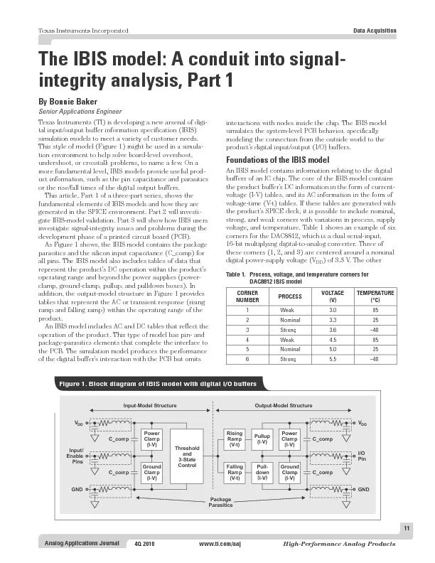
4Q 2010wwwticomaajHighPerformance Analog ProductsThe IBIS model A conduit into signal integrity analysis Part 1Texas Instruments TI is developing a new arsenal of digital inputoutput buffer ID: 292804

2010www.ti.com/aajHigh-Performance Analog ProductsThe IBIS

Share:

Link:

Embed:

Download Presentation from below link

Download Pdf The PPT/PDF document "Analog Applications JournalTexas Instrum..." is the property of its rightful owner. Permission is granted to download and print the materials on this web site for personal, non-commercial use only, and to display it on your personal computer provided you do not modify the materials and that you retain all copyright notices contained in the materials. By downloading content from our website, you accept the terms of this agreement.


Presentation Transcript

Analog Applications JournalTexas Instruments Incorporated 4Q 2010www.ti.com/aajHigh-Performance Analog ProductsThe IBIS model: A conduit into signal- integrity analysis, Part 1Texas Instruments (TI) is developing a new arsenal of digital input/output buffer information specification (IBIS) simulation models to meet a variety of customer needs. This style of model (Figure 1) might be used in a simulation environment to help solve board-level overshoot, undershoot, or crosstalk problems, to name a few. On a more fundamental level, IBIS models provide useful product information, such as the pin capacitance and parasitics or the rise/fall times of the digital output buffers.This article, Part 1 of a three-part series, shows the fundamental elements of IBIS models and how they are generated in the SPICE environment. Part 2 will investi *TexasIntrumacxoaxcr*TexaV gssa Table 1.Process, voltage, and temperature corners for DAC8812 IBIS model VOLTAGETEMPERATUREWeakNominal3WeakNominal5 Texas Instruments Incorporated Analog Applications Journal High-Performance Analog Productswww.ti.com/aaj4Q 2010Data Acquisitionthree corners (4, 5, and 6) are centered around a nominal V of 5.0 V.An IBIS model created at the bench is limited to the tests from one to a few devices. The bench-tested IBIS models usually do not show silicon-process variations.IBIS models can contain data for any of several different buffer types: input, output, I/O, tri-state, terminator, output_open_source, output_open_sink, I/O_open_source, I/O_open_sink, input_ECL, output_ECL, and I/O_ECL.The voltage at an input or output buffer’s pin in the DC tables extends beyond the supply voltage (V) from to 2 × V. This exercises the product buffer’s ESD structures beyond the supply voltage. In this manner, IBIS models are capable of showing the overshoot and under- shoot responses of poorly terminated PCB signals. IBIS models contain I-V data for input and output buffers.The example of an input buffer in Figure 2 shows the input buffer, the ESD cells, and the buffer’s capacitance (C_comp). An IBIS model for an input buffer provides I-V tables of data that extend beyond ground and the supply Figure 3. Graphical representation of IBIS model’s I-V tables kQ ly0BM xas FtNGkQ ly0BM I*nI FtNG Figure 2. Example of input buffer’s basic functionality voltage (V). Note that the IBIS model does not require circuitry beyond the immediate interface. IBIS models do not reflect the product’s interior logic and interactions. Figure 3 shows a composite graphical example of an input buffer’s power-clamp and ground-clamp I-V tables from an IBIS model. Texas Instruments Incorporated Analog Applications Journal 4Q 2010www.ti.com/aajHigh-Performance Analog ProductsData AcquisitionV-t tables represent the AC behavior of an output buffer like the one in Figure 4. With V-t tables, the output buffer’s pin remains inside the product’s power-supply rails. IBIS models are capable of simulating the buffer within its operating range, exhibiting accurate simulations of rise and fall times.Figure 4 shows the pullup and pulldown circuitry as well as the input capacitance of a two-state output buffer. With the output buffer, an IBIS model will typically have I-V tables as well as V-t tables. Once again, the IBIS model does not require circuitry beyond the immediate interface because the model does not reflect the product’s interior logic and interactions. Figure 5 shows a graphical example of the rising-time waveform from an IBIS model’s V-t table. IBIS model’s V-t table lS ycMx axmtcaxo iBa efx Btente eB kgce#f iaBM DrV2S ycMx axmtcaxo iBa efx Btente eB kgce#f iaBM A*PAeB DrV RisII5ecMx oses1S Figure 4. Example of two-state output buffer’s basic functionality Texas Instruments Incorporated Analog Applications Journal High-Performance Analog Productswww.ti.com/aaj4Q 2010Data AcquisitionThe format of the IBIS model starts with a header, which is generated by hand and includes a description of the relevant IC or ICs. Following the IC description is general information about the model, including origination date, model source, and user notes. Figure 6 shows an example header of an IBIS model for TI’s TMP512 and TMP513, which are temperature and supply-system monitors with an SMBus interface. The “Notes” section is the most important portion of the IBIS model header, where details of the model creation are found along with the basic format of the digital buffers.The model header is followed by detailed information about the package(s) for the product(s), including values for pin resistance, inductance, and capacitance. To find the total capacitance for a specific pin, the capacitance values in this section are combined with the capacitance (C_comp) values called out next in the buffer tables. The core of the IBIS model follows with I-V and V-t tables buffer by buffer.The last section of this article will explain how to obtain the I-V and switching information (V-t) from a buffer’s transistor-level model. An automated simulation template, an extraction tool (such as S2IBIS3), or manual simulations can be used. This discussion will include only totem-pole CMOS structures.To extract the I-V data for an IBIS model from a SPICE input buffer, the buffer pad is connected to an independent voltage source (V). Once the buffer’s input is set to its desired state (LOW, HIGH, or OFF), V is exercised with a DC-analysis function over the sweep range of –V to 2 × V, where the V limit is set by the product’s supply voltage (V). For instance, if the buffer is powered by a 5-V supply, the range of Vwill be –5 V to 10 V. While performing this sweep, the simulator records the current that goes into the buffer.If the buffer is configured in a high-impedance state (OFF), the data collected produces the ground-clamp and power-clamp tables. The data in the ground-clamp table is referenced to ground, and the data in the power-clamp table is referenced to VExtracting the I-V data for an output buffer’s IBIS model results in a pulldown table and a pullup table. Data for the pulldown table is collected while the buffer is in an output LOW state. Data for the pullup table is collected while the buffer is in an output HIGH state. Data in the pulldown table is referenced to ground, and data in the pullup table is referenced to V |Texas Instruments Incorporated|Temperature and Supply System MonitorsSMBusinterface| Marketing part#Digital VoltageAnalog Voltage Package|RangeRangeType|TMP512AIDG42.1V to 3.6V 3.0V to 26V SO-14 14|TMP512AIDRG42.1V to 3.6V 3.0V to 26V SO-14 14|TMP513AIDG42.1V to 3.6V 3.0V to 26V SO-16 16|TMP513AIDRG42.1V to 3.6V 3.0V to 26V SO-16 16|TMP513AIRSATG42.1V to 3.6V 3.0V to 26V QFN-16 16Ve[Source]Texas Instruments Incorporated.Analog-eLab, HPA12500TI BlvdDallas,TX-75243e--Initial version of the model-Initial Model generated from simulations inTISPICED-M-Non-monotnicwarnings-combinedpulldownandpullupdataThe GPIO non-monotonic current delta is less than 1 mAin afull-scale range of ~95 mA. Given these conditions, theseThis product is designed as an aid for customers ofTexas Instruments.particular purpose is claimed byTexas Instruments or the author.Tsoftware (if any) is provided solely on an "as is" basis.The entire[Copyright] (C) Copyright 2009Texas Instruments Incorporated. Extracting V-t data from SPICE simulationsWhen a CMOS buffer is modeled, the required simulations that relate to the ramp rate and V-t tables are straightforward. For each simulation corner (typical, minimum, and maximum), there are four V-t data sets. Data for two of the waveforms is gathered by switching the buffer output from LOW to HIGH with the load referenced to a low voltage. Data for the other two waveforms is collected with a load referenced to V. For the latter two curves, the buffer’s output switches from HIGH to LOW. From these simulations, the ramp rate or dV/dt ratio is extracted as the device is switching HIGH against a low-voltage reference and switching LOW against a high-voltage reference. Texas Instruments Incorporated Analog Applications Journal 4Q 2010www.ti.com/aajHigh-Performance Analog ProductsData AcquisitionThere is a variety of buffer types that the IBIS standard describes with I-V and V-t tables. Tables 2 and 3 from Reference 1 list the required and recommended buffer data for each type of buffer.An IBIS model assists PCB designers during their evaluations of signal-integrity issues and problems. The model’s silicon-based DC and AC data facilitates the evaluation of over-power-supply behavior as well as rise- and fall-time behavior. In Part 2, the validity of the IBIS model will be evaluated by verifying that it meets IBIS standards and by comparing it to SPICE simulations. [Rising Waveform] [Falling Waveform] Model_typ Load to Vcc Load to GND Load to Vcc Load to GND Note Input n/a n/a n/a n/a I/O Recommended Recommended Recommended Recommended I/O_open_drain Recommended n/a Recommended n/a 1 I/O_open_source n/a Recommended n/a Recommended 1 I/O_open_sink I/O_open_drainRecommended n/a Recommended n/a 1 Open_source n/a Recommended n/a Recommended Open_sink Open_drainRecommended n/a Recommended n/a 3-state Recommended Recommended Recommended Recommended Series_switch n/a n/a n/a n/a 2 Series n/a n/a n/a n/a 2 Output Recommended Recommended Recommended Recommended Termn/a n/a n/a n/a Input_ECL n/a n/a n/a n/a I/O_ECL Recommended (to Vcc – 2) Recommended (to Vcc – 2) 3 Recommended (to Vcc – 2) Recommended (to Vcc – 2) 3 3-state_ECL Recommended (to Vcc – 2) 3 1. The presence of internal terminations may require adding waveforms in place of “n/a” 2. Special syntax required using the same load impedance may beuseful in some contexts Table 3. Required and recommended V-t data versus IBIS buffer types Model_typ [Pullup] [Pulldown] [POWER Clamp] [GND Clamp] Note Input n/a n/a Recommended Recommended I/O Required Required Recommended Recommended I/O_open_sink I/O_open_drainn/a Recommended Recommended 1 I/O_open_source n/a Recommended Recommended 1 Open_sink Open_drainn/a Recommended Recommended 4 Open_source n/a Recommended Recommended 4 Output Required Required Recommended Recommended 4 3-state Required Required Recommended Recommended 2 Series_switch n/a n/a n/a n/a 3 Series n/a n/a n/a n/a 3 Termn/a n/a Recommended Recommended 3 Input_ECL n/a n/a Recommended Recommended I/O_ECL Required Required Recommended Recommended 2 Output_ECL Required Required Recommended Recommended 4 3-state_ECL Required Required Recommended Recommended 2 1. Keywords listing “n/a” may be included if the currents are set to 0 for all voltage points 3. Special syntax required; use of clamp data on pins that4. Clamp data may technically be excluded; however, this data aids analysis of reflections arriving at the driving buffer Table 2. Required and recommended I-V data versus IBIS buffer typesThe IBIS Open Forum. (2005, Sept. 15). IBIS Modeling Cookbook for IBIS Version 4.0 [Online]. Available: www.eda.org/ibis/cookbook/cookbook-v4.pdfRoy Leventhal and Lynne Green, Semiconductor Modeling for Simulating Signal, Power, and Electromagnetic Integrity. New York: Springer Science+Business Media, LLC, 2006.Related Web sitesdataconverter.ti.comwww.ti.com/sc/device/DAC8812www.ti.com/sc/device/TMP512www.ti.com/sc/device/ TMP513Tables 2 and 3 from Reference 1 reproduced with permission of the IBIS Open Forum and TechAmerica. © 2010 Texas Instruments Incorporated E2E is a trademark of Texas Instruments. All other trademarks are the property of SLYT TI Worldwide Technical Support Internet Home PageTI E2E™ Community Home Page Phone+1(972) 644-5580 Brazil Phone0800-891-2616 Mexico Phone0800-670-7544 Fax+1(972) 927-6377 Internet/Email Europe, Middle East, and Africa European Free Call00800-ASK-TEXAS International+49 (0) 8161 80 2121 Russian Support+7 (4) 95 98 10 701 The European Free Call (Toll Free) number is not active in all countries. If you have technical difficulty calling the free call number, please use the international number above. Fax+(49) (0) 8161 80 2045 Internet support.ti.com/sc/pic/euro.htJapan PhoneDomestic0120-92-3326 FaxInternational+81-3-3344-5317 Domestic0120-81-0036 Internet/EmailInternational support.ti.com/sc/pic/japan.ht Domestic www.tij.co.jp/pi Asia Phone International+91-80-41381665 Domestic Toll-Free Number Taiwan Fax+886-2-2378-6808 Internet The products and services of Texas Instruments Incorporated and its subsidiaries described herein are sold subject to TI’s standard terms and conditions of sale. Customers are advised to obtain the most current and complete information about TI products and services before placing orders. TI assumes no liability for applications assistance, customer’s applications or product designs, software performance, or infringement of patents. The publication of information regarding any other company’s products or services does not constitute TI’s approval, warranty IMPORTANTNOTICETexasInstrumentsIncorporatedanditssubsidiaries(TI)reservetherighttomakecorrections,modifications,enhancements,improvements,andotherchangestoitsproductsandservicesatanytimeandtodiscontinueanyproductorservicewithoutnotice.Customersshouldobtainthelatestrelevantinformationbeforeplacingordersandshouldverifythatsuchinformationiscurrentandcomplete.AllproductsaresoldsubjecttoTI’stermsandconditionsofsalesuppliedatthetimeoforderacknowledgment.TIwarrantsperformanceofitshardwareproductstothespecificationsapplicableatthetimeofsaleinaccordancewithTI’sstandardwarranty.TestingandotherqualitycontroltechniquesareusedtotheextentTIdeemsnecessarytosupportthiswarranty.Exceptwheremandatedbygovernmentrequirements,testingofallparametersofeachproductisnotnecessarilyperformed.TIassumesnoliabilityforapplicationsassistanceorcustomerproductdesign.CustomersareresponsiblefortheirproductsandapplicationsusingTIcomponents.Tominimizetherisksassociatedwithcustomerproductsandapplications,customersshouldprovideadequatedesignandoperatingsafeguards.TIdoesnotwarrantorrepresentthatanylicense,eitherexpressorimplied,isgrantedunderanyTIpatentright,copyright,maskworkright,orotherTIintellectualpropertyrightrelatingtoanycombination,machine,orprocessinwhichTIproductsorservicesareused.InformationpublishedbyTIregardingthird-partyproductsorservicesdoesnotconstitutealicensefromTItousesuchproductsorservicesorawarrantyorendorsementthereof.Useofsuchinformationmayrequirealicensefromathirdpartyunderthepatentsorotherintellectualpropertyofthethirdparty,oralicensefromTIunderthepatentsorotherintellectualpropertyofTI.ReproductionofTIinformationinTIdatabooksordatasheetsispermissibleonlyifreproductioniswithoutalterationandisaccompaniedbyallassociatedwarranties,conditions,limitations,andnotices.Reproductionofthisinformationwithalterationisanunfairanddeceptivebusinesspractice.TIisnotresponsibleorliableforsuchaltereddocumentation.InformationofthirdpartiesmaybesubjecttoadditionalResaleofTIproductsorserviceswithstatementsdifferentfromorbeyondtheparametersstatedbyTIforthatproductorservicevoidsallexpressandanyimpliedwarrantiesfortheassociatedTIproductorserviceandisanunfairanddeceptivebusinesspractice.TIisnotresponsibleorliableforanysuchstatements.TIproductsarenotauthorizedforuseinsafety-criticalapplications(suchaslifesupport)whereafailureoftheTIproductwouldreasonablybeexpectedtocauseseverepersonalinjuryordeath,unlessofficersofthepartieshaveexecutedanagreementspecificallygoverningsuchuse.Buyersrepresentthattheyhaveallnecessaryexpertiseinthesafetyandregulatoryramificationsoftheirapplications,andacknowledgeandagreethattheyaresolelyresponsibleforalllegal,regulatoryandsafety-relatedrequirementsconcerningtheirproductsandanyuseofTIproductsinsuchsafety-criticalapplications,notwithstandinganyapplications-relatedinformationorsupportthatmaybeprovidedbyTI.Further,BuyersmustfullyindemnifyTIanditsrepresentativesagainstanydamagesarisingoutoftheuseofTIproductsinsuchsafety-criticalapplications.TIproductsareneitherdesignednorintendedforuseinmilitary/aerospaceapplicationsorenvironmentsunlesstheTIproductsarespecificallydesignatedbyTIasmilitary-gradeor"enhancedplastic."OnlyproductsdesignatedbyTIasmilitary-grademeetmilitaryspecifications.BuyersacknowledgeandagreethatanysuchuseofTIproductswhichTIhasnotdesignatedasmilitary-gradeissolelyattheBuyer'srisk,andthattheyaresolelyresponsibleforcompliancewithalllegalandregulatoryrequirementsinconnectionwithsuchuse.TIproductsareneitherdesignednorintendedforuseinautomotiveapplicationsorenvironmentsunlessthespecificTIproductsaredesignatedbyTIascompliantwithISO/TS16949requirements.Buyersacknowledgeandagreethat,iftheyuseanynon-designatedproductsinautomotiveapplications,TIwillnotberesponsibleforanyfailuretomeetsuchrequirements.FollowingareURLswhereyoucanobtaininformationonotherTexasInstrumentsproductsandapplicationsolutions: Audiowww.ti.com/audio DataConverters Automotivewww.ti.com/automotive DLP®Products Communicationsand TelecomDSPdsp.ti.com Computersand ClocksandTimers ConsumerElectronics Interfaceinterface.ti.com Energywww.ti.com/energy Logiclogic.ti.com Industrialwww.ti.com/industrial PowerMgmt Medicalwww.ti.com/medical Microcontrollersmicrocontroller.ti.com Securitywww.ti.com/security RFIDwww.ti-rfid.com Space,Avionics& RF/IFandZigBee®Solutions VideoandImaging Wirelesswww.ti.com/wireless-apps MailingAddress:TexasInstruments,PostOfficeBox655303,Dallas,Texas75265Copyright©2010,TexasInstrumentsIncorporated