/
Analog Applications Journal November  Analog and MixedSignal Products exas Instruments Analog Applications Journal November  Analog and MixedSignal Products exas Instruments

Analog Applications Journal November Analog and MixedSignal Products exas Instruments - PDF document

test
test . @test
Follow
547 views
Uploaded On 2014-12-13

Analog Applications Journal November Analog and MixedSignal Products exas Instruments - PPT Presentation

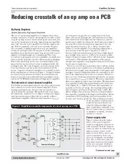
ticom Reducing crosstalk of an op amp on a PCB The use of operational amplifiers is common these days In many instances it can be advantageous to utilize a dual or quad op amp to save circuit board space and costs but one of the drawbacks is that the ID: 23438

ticom Reducing crosstalk

Share:

Link:

Embed:

Download Presentation from below link

Download Pdf The PPT/PDF document "Analog Applications Journal November An..." is the property of its rightful owner. Permission is granted to download and print the materials on this web site for personal, non-commercial use only, and to display it on your personal computer provided you do not modify the materials and that you retain all copyright notices contained in the materials. By downloading content from our website, you accept the terms of this agreement.


Presentation Transcript

23Analog Applications Journal November 1999Analog and Mixed-Signal ProductsTexas Instruments IncorporatedAmplifiers: Op Ampsamplifier.ti.comReducing crosstalk of an op amp on a PCBThe use of operational amplifiers is common these days.In many instances, it can be advantageous to utilize a dual-age.This is commonly referred to as crosstalk. To mea-sure crosstalk, a signal is applied to only one amplifierare several notes and papers on how to minimize crosstalk,butthese typically deal only with the silicon and/or packaging.-talk in the TI THS4052 dual-channel high-speed amplifier.The internals of a dual-channel amplifierIt is helpful to understand what the user does and does not. Whenbuying a packaged part, the user has no control over -tant internal structures that lead to crosstalk within a. Both internal inductors (LInternal)on each power-supply line are comprised of the lead- PCBPadL+V TraceL+V TraceL-V TraceL-V TraceLInternalLInternalCBypassCBypassLGround TracePCBPad+V-VPCBPadsOutOutCh. 1CircuitryCh. 2CircuitryCInternalCStr +Ð+Ð Figure 1. Simplified crosstalk components of a dual op amp on a PCB Continued on next page Texas Instruments IncorporatedAmplifiers: Op Amps 24Analog Applications Journal Analog and Mixed-Signal ProductsNovember 1999amplifier.ti.cominductance on the power supplyonly gets worse. In fact, theThe cure for this inductanceproblem is easy to implementphysically as close aspossible to the op amp power-supplypins. When it comes todealing with high-frequency-ical. These bypass capacitorsshould have very good high-frequency characteristics, whichthe use oflarge electrolytic or tantalumcapacitors. Large ÒbulkÓ capaci-tors play an importantrole insupplying lower-frequency cur-rents, but they do not performThe most common type ofcapacitor used for high-. Using surface-mount technology (SMT) components over leaded parts, making the capacitor behavemore like the ÒidealÓ capacitor. To see the benefits, theground side of the bypass capacitors should always beas possible. The trace is an inductor at high frequencies,.There are numerous other ideas to improve power-supplydecoupling, but they tend to cost more and consume 1For most circuits, though, the useof a simple 0.1-µF or 0.01-µF ceramic capacitor in parallelwith a large tantalum or electrolytic capacitor will provide-supply decoupling.A few tests will illustrate the effects of power-supplydecoupling. These tests were done using a THS4052 ADTMpackage. Because this amplifier has a bandwidth of 70As Figure 3 shows, removing the 0.1-µF capacitorsmade the crosstalk worse by almost 10 dB at 10 MHz andµF tantalum bypass capacitors were also removedto see the effects on crosstalk. As expected, the crosstalkLooking at Figure 1, we see that the supply voltages(+V and ÐV) should not cause any changes in crosstalko verify if this was true, the results for allthe tests conducted throughout this application note were±15-V and ±5-V supplies. As expected, thecrosstalk performances with different supply voltages. Thepower supplies do not play any significant role with -80-70-60-50-40-30-20-100100.1110100Crosstalk (dB)Frequency (MHz) No 0.1-µFCapacitors No BypassCapacitors With All BypassCapacitors Figure 3. Power-supply decouplingcrosstalk results 0.1 µFR150LOADWR150LOADW50WR= 1 kGWR= 1 kGWR= 1 kFWR= 1 kFW0.1 µF22 µF+15 VÐ15 V50W22 µF +Ð HP85024AProbeHP8753ENetworkAnalyzerPort 2Port 1THS4052Ch.2+ÐCh.1 Figure 2. Default test circuit set-up configuration Continued from previous page Texas Instruments IncorporatedAmplifiers: Op Amps 25Analog Applications Journal November 1999Analog and Mixed-Signal Productsamplifier.ti.comOne question arises from this figure. Why does thecrosstalk start dropping again at high frequencies whenthere are no bypass capacitors? There are two answers.gain of +2, the bandwidth of this voltage feedback ampli-fierwill be around only 35 MHz (following the traditionalgain-bandwidth product). Above this frequency, the ampli-tudeof both amplifiers starts to drop off and the currentdemand on the power supply is also reduced, minimizingThe second answer is that the utilization of a groundplane on the PCB helps minimize the lead inductance-supply trace runs on top of theground plane, some distributed capacitance is formed.µF capacitor, because theequivalent capacitance value is much less.Taking this idea the next step, a power plane for eachsupply voltage and at least one ground plane can signifi-cantly increase the high-frequency power-supply bypassingeffects. The first thing this does is to minimize the tracepro-vided by power planes is a very large, uniformly distributed-supply bypass capacitor. This capacitance can beextremely helpful when dealing with frequencies greaterGround Traceinductance. This can beeasily accomplished by filling the unused portions of theAmplifier resistor selectionNo matter how an amplifier is used, resistors are used tohave no choice in the resistances used to close the ampli-fier loop. But, if any resistor value can be chosen, thereAs shown in Figure 1, the output pins and input pinscan couple into each other by stray capacitances. Notice-come just about any form of crosstalk coupling.The same does not hold true when it comes to theinverting and non-inverting input pins of the amplifier.This is because the input impedance of these pins is gen-erally very high. In the case of FET amplifiers, it can12ohms. This is very important because theamount of stray capacitance required to inject a signal isC) is equal to the nodalresistance, the amount of signal injection has reached the-ancecan be lowered, the effects of the stray capacitancecan be reduced.This idea is the basis for the next design rule to helpreduce crosstalk. Simply use smaller resistances for both. Forthe inverting node, which must have a feedback resistorF) and usually a gain resistor (RG), the ac nodal resist-ance is equivalent to the parallel resistance of both ofAD package. The test circuit shown inFigure 2 was also used for this test, with the resistor The amplifiers were placed into a gain of +2 by makingthe feedback (RF) and gain (RG) resistor values equal toeach other. It can be seen that as the ac resistance value -80-70-60-50-40-30-20 R= 4.7 kFW MSOP PowerPADGain = +2R= 150LW R= 1 kFW 0.1110100Crosstalk (dB)Frequency (MHz) Figure 5. Effects of feedback and gainresistors on crosstalkÑMSOP -80-70-60-50-40-30-20 R= 4.7 kFW SOICGain = +2R= 150LW R= 1 kFW 0.1110100Crosstalk (dB)Frequency (MHz) Figure 4. Effects of feedback and gainresistors on crosstalkÑSOIC Continued on next page Texas Instruments IncorporatedAmplifiers: Op Amps 26Analog Applications Journal Analog and Mixed-Signal ProductsNovember 1999amplifier.ti.com -80-70-60-50-40-30-20 R= 150LOADW SOICGain = +2R= 1 kFW R= 1 kLOADW 0.1110100Crosstalk (dB)Frequency (MHz) Figure 6. Effects of load resistance oncrosstalkÑSOIC -80-70-60-50-40-30-20 R= 150LOADW MSOP PowerPADGain = +2R= 1 kFW R= 10 kLOADW R= 1 kLOADW 0.1110100Crosstalk (dB)Frequency (MHz) Figure 7. Effects of load resistance oncrosstalkÑMSOP -80-70-60-50-40-30-20 G = +5 G = -1 G = +2 G = +1 SOICR= 1 kFWR= 150 kLW 0.1110100Crosstalk (dB)Frequency (MHz) Figure 8. Effects of gain and configuration oncrosstalkÑSOIC Continued from previous pageat the inverting node decreased, the crosstalk alsodecreased, especially for the SOIC package. However,there may be some drawbacks to reducing the resistor. Another thing that istypically overlooked is that the feedback resistor is also. What happens as theload is increased on the amplifier?Amplifier loading effectsRecall from the first section that trace inductances, bothF) becoming the dominant load to the amplifier. In gen-eral, the higher the load resistance on the amplifier, thelower the crosstalk will become.Amplifier configuration considerationsUp to this point all of the results have been shown with theThe first thing to try is changing the non-inverting gainfrom +2 to different values. This usually brings up somewill be amplifying the crosstalk signal by only a small gain, a gain of Ð1 is equiv-alent to a noise gain of +2. So the only thing that reallys input. The measuredamplifier is held in the exact same configuration as a gainFigures 8 and 9 show the results of different gains andconfigurations. For all gains shown, the feedback resistanceF) was held at 1 kW, and the gain resistor (RG) wasadjusted accordingly. Both amplifiers were also configuredthe same way such that if Channel 2 was set in a gain ofThe results speak for themselves. It appears that as thegain increases, the crosstalk becomes much worse. It also Texas Instruments IncorporatedAmplifiers: Op Amps 27Analog Applications Journal November 1999Analog and Mixed-Signal Productsamplifier.ti.comthe test set, surpassing the gain of +2 by a fairly respectablemargin. By the non-inverting node being held at ground-ence. Traditionally, this usually keeps the common-moderejection ratio (CMRR) of the amplifier at its best perform-ance.As long as the stray capacitances and noise levelsare held fairly close to each other at both of the input nodes,.One last configuration to try was the non-invertingbuffer configuration with no feedback resistance (RF= 0 W).This will keep the inverting node impedance very small.Figures 10 and 11 show that this configuration is the abso-lutebest when it comes to dealing with crosstalk issues.The problem with this configuration is that typically theWfeedback resistance. This is especially true forcurrent feedback amplifiers that must have a feedback-cation note is to show real-world situations, and this unityPackaging and layout considerationsThe next thing that plays a role in crosstalk is packaging., SOIC, MSOP, or TSSOP.The packages may give a clue as to which might perform. Remember that the circuit designer has no controlover the internals of the package, so selecting the smallestAD package,where the MSOP is substantially the smaller of the two.In order to see the results of these packages, they mustbe placed on a circuit board. The PCBs used for all thesetests were practically identical. Only the landing area for. The MSOP packagehas a PowerPAD on the bottom of the chip to improve heatdissipation of the small package. The advantage of this is-fier via the ground plane, before the signal couples into.The SOIC-packaged amplifier, on the other hand, doesnot require a ground plane between the pins. The test. This does not represent a low-impedance sink to the crosstalk signals. To see if adding aground area actually does anything, a piece of copper -80-70-60-50-40-30-20 G = +5 G = -1 G = +2 G = +1 MSOP PowerPADR= 1 kFWR= 150LW 0.1110100Crosstalk (dB)Frequency (MHz) Figure 9. Effects of gain and configuration oncrosstalkÑMSOP Continued on next page -90-80-70-60-50-40-30SOICGain = +1R= 0FWR= 150LOADW0.1110100Crosstalk (dB)Frequency (MHz)R= 1 kLOADW Figure 10. Crosstalkwith unity gain bufferconfigurationÑSOIC -90-80-70-60-50-40-30MSOP PowerPADGain = +1R= 0FWR= 150LOADW0.1110100Crosstalk (dB)Frequency (MHz)R= 1 kLOADW Figure 11. Crosstalkwith unity gain bufferconfigurationÑMSOP Texas Instruments IncorporatedAmplifiers: Op Amps 28Analog Applications Journal Analog and Mixed-Signal ProductsNovember 1999to the ground plane to simulate the MSOP PowerPADconfiguration.Figures 12 and 13 show the results of the differentpackages. Again, the gain of Ð1 configuration shows thebest real-situation results. The addition of the groundAD package.There are two reasons for this. The first is the physicalsize of the MSOP PowerPAD package. It is smaller thanthe SOIC package, reducing inductances. Second, theAD keeps the substrate of the silicon at a groundreference. Thus the two channels inside the package have-strate to act as a noise-coupling device into the adjacento keep thesubstrate at a fixed level, it is fairly common to connect-supply pins to the substrate. The draw-back is that the pin itself has the same lead inductance asIt cannot be denied that a ground plane does improvethe SOIC crosstalk response. Instead of placing a ground-supply tracesbetween the leads would also serve the same purpose as-supply traces will not have as low an inductance,and hence impedance, as a true ground plane. Another-supply noise also may be capaci-tively coupled into the chip by the traces being directly-supply plane shouldremedy all of these possible problems.General design guidelines and conclusionsThe results of this testing have shown several things tobased on experience and extrapolation of this data. The1.Use 0.1-µF or 0.01-µF SMT ceramic bypass capacitorsas close as possible to the power-supply pins on eachand every amplifier.2.Use a very large ground plane on the PCB.3.Use a power-supply plane for each supply voltage ifpossible.4.The best crosstalk performance is achieved with again of +1 configured with a 0-Wfeedback resistance.But, for most applications, use a gain of Ð1 if possible.5.Keep the amplifier gain to a minimum.6.Keep the feedback (RF) and gain (RG) resistancesdown to a minimum.7.Use as high a load resistance as your design allows.8.Pick a small surface-mount (SMT) package.9.Consider the PowerPAD package with the pad soldered directly to the ground plane.10.If using a non-PowerPAD package, place a ground pador low-impedance traces between the pins.11.Keep non-inverting and inverting pin traces to a 12.If design allows, put guard traces around the input. This guard trace should be con-nected to the ground plane for high isolation.13.Keep the ground return path of the load routed aways input traces.14.Isolate the traces for each amplifier from the otherFollowing these rules should minimize crosstalk issuesin PCB design and allow the user of multi-amplifier pack-ages to save PCB space and money.Reference1.Jerald Graeme, Optimizing Op Amp Performance(NY: McGraw-Hill, 1997), pp. 73-105.amplifier.ti.comContinued from previous page -80-70-60-50-40-30-20 SOIC Gain = +2R= 1 kFWR= 150LW SOIC +Isolation MSOPPowerPAD 0.1110100Crosstalk (dB)Frequency (MHz) Figure 12. Effects of packaging and PCB oncrosstalkÑGain = +2 -80-70-60-50-40-30-20 SOIC Gain = -1R= 1 kFWR= 1 kLW SOIC +Isolation MSOPPowerPAD 0.1110100Crosstalk (dB)Frequency (MHz) Figure 13. Effects of packaging and PCB oncrosstalkÑGain = Ð1 IMPORTANT NOTICE Texas Instruments Incorporated and its subsidiaries (TI) reservestandard warranty. Testing and other quality control techniques areused to the extent TI deems necessary to support this warranty.applications using TI components. To minimize the risksunder the patents or other intellectual property of the third party, or aTexas Instruments products and application solutions: TIWorldwide Technical Support InternetTI Semiconductor Product Information Center Home Pagesupport.ti.comTI Semiconductor KnowledgeBase Home Pagesupport.ti.com/sc/knowledgebase Phone+1(972) 644-5580Fax+1(972) 927-6377 Internet/Emailsupport.ti.com/sc/pic/americas.htmBelgium (English)+32 (0) 27 45 54 32Netherlands (English)+31 (0) 546 87 95 45Finland (English)+358 (0) 9 25173948Russia+7 (0) 95 7850415France+33 (0) 1 30 70 11 64Spain+34 902 35 40 28Germany+49 (0) 8161 80 33 11Sweden (English)+46 (0) 8587 555 22Israel (English)1800 949 0107United Kingdom+44 (0) 1604 66 33 99Italy800 79 11 37Fax+(49) (0) 8161 80 2045 Internetsupport.ti.com/sc/pic/euro.htmInternational+81-3-3344-5317Domestic0120-81-0036Internationalsupport.ti.com/sc/pic/japan.htm Domesticwww.tij.co.jp/picInternational+886-2-23786800DomesticToll-Free NumberToll-Free NumberAustralia1-800-999-084New Zealand0800-446-934China800-820-8682Philippines1-800-765-7404Hong Kong800-96-5941Singapore800-886-1028Indonesia001-803-8861-1006Taiwan0800-006800Korea080-551-2804Thailand001-800-886-0010Malaysia1-800-80-3973Fax886-2-2378-6808Emailtiasia@ti.comInternetsupport.ti.com/sc/pic/asia.htmti-china@ti.com of similar import. Similarly, such statements herein that describethe company's products, business strategy, outlook, objectives,of operations. We disclaim any intention or obligation to updateTrademarks: PowerPAD is a trademark of Texas Instruments. AllMailing Address: Texas InstrumentsDallas, Texas 75265 © 2005 Texas Instruments Incorporated amplifier.ti.comdataconverter.ti.compower.ti.com microcontroller.ti.comwww.ti.com/audiowww.ti.com/automotivewww.ti.com/broadbandwww.ti.com/digitalcontrolwww.ti.com/militarywww.ti.com/opticalnetworkwww.ti.com/securityTelephony www.ti.com/telephony Video & Imaging www.ti.com/videowww.ti.com/wireless SLYT190