/
Vehicle Speed Limit Alerting and Crash Detection Syste Vehicle Speed Limit Alerting and Crash Detection Syste

Vehicle Speed Limit Alerting and Crash Detection Syste - PDF document

min-jolicoeur
min-jolicoeur . @min-jolicoeur
Follow
438 views
Uploaded On 2015-04-25

Vehicle Speed Limit Alerting and Crash Detection Syste - PPT Presentation

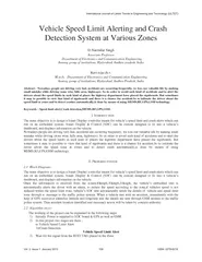
Narendar Singh Associate Professor Department of Electronics and Communication Engineering Anurag group of institutions Hy derabad Andhra pradesh India Ravi teja chv Mtech Department of Electroni cs and Communication Engineering Anurag group of insti ID: 55156

Narendar Singh Associate Professor Department

Share:

Link:

Embed:

Download Presentation from below link

Download Pdf The PPT/PDF document "Vehicle Speed Limit Alerting and Crash D..." is the property of its rightful owner. Permission is granted to download and print the materials on this web site for personal, non-commercial use only, and to display it on your personal computer provided you do not modify the materials and that you retain all copyright notices contained in the materials. By downloading content from our website, you accept the terms of this agreement.


Presentation Transcript

4)RFID reader reads the tag.If signal valid, the vehicle’s embedded unit is automatically alerts the driver with an alarm, to reduce the speed according to the zone. 5)Here we are showing by “PRESS THE BUTTON TO STOP THE ALARM” which indicates that driver reduced speed. 6)Otherwise,after few seconds vehicle’s SDC unit automatically sends the details of vehicle and zone “VEHICLE NO:AP10 2345 MOVIING OVER SPEED AT ZONE” through a message using GSM module to the registered mobile number. Figure 1. Vehicle speed limit alerting and crash detection system Block Diagram Crash Detection 7)When the vehicle gets accident here we are showing by “SHAKE THE MEMS TO KNOW THE THAT ACCIDENT OCCURED”. So, by shaking the button the MEMS SENSOR will start up the process. 8)Then the ARM controller will activate the GSM module. 9)The GSM module will send the message “ACCIDENT OCCURRED AT FOLLOWING LOCATION 10)In this latitude and longitude values will be taken through the GPS module by using GSM it send the message to the registered mobile number by which victims can be saved. 2.3Flow chart- ARM Display Section RFID Reader Power supply GPS GSM Modem Alarm Unit Mems sensor SECTION VEHICLE SECTIONVol. 2 Issue 1 January 2013109ISSN: 2278-621X of these satellites, it can triangulate its location from the known positions of the satellites. In my paper when accident occurs tha GPS receiver finds the latitude and longitude values so that the accident location is find out and the victims can be rescued. GSM (Global System for Mobile communications) is an open, digital cellular technology used for transmitting mobile voice and data services. GSM uses a variation of Time Division Multiple Access (TDMA) and is the most widely used of the three digital wireless telephone technologies (TDMA, GSM, and CDMA. It operates at either the 900 MHz or 1,800 MHz frequency band. It supports voice calls and data transfer speeds of up to 9.6 kbit/s, together with the transmission of SMS (Short Message Service). In my paper GSM modem is used at two points. One is when the driver exceeds speed limits at speed limit zone, the vehicle and the speed limit zone details are sent to the traffic police system using GSM modem. Other is when accident occurs location values are taken from GPS receiver and sent through GSM modem. Accident Detection Module(MEMS) An MEMS accelerometer measures acceleration (change in speed) of anything that it's mounted on. Single axis accelerometers measure acceleration in only one direction.Dual-axis accelerometers, which are the most common, measure acceleration in two directions, perpendicular to each other. Three-axis accelerometers measure acceleration in three directions. Accelerometers are very handy for measuring the orientation of an object relative to the earth, because gravity causes all objects to accelerate towards the earth. A two-axis accelerometer can be used to measure how level an object is with a three-axis accelerometer, you can measure an object's acceleration in every direction.In my paper when the MEM sensor is shaked it assumes that the accident occurred. RFID Module RFID tags come in a wide variety of shapes and sizes. Animal tracking tags, inserted beneath the skin, can be as small as a pencil lead in diameter and one-half inch in length The RFID modules are of different kinds. But, In this paper we are using three RFID passive tags which are placed in the three different speed limit zones. These tags get detected by the RFID reader when the vehicle enters into the zone as FRID reader is fixed in the vehicle. So, when vehicle enters the speed limit zone the RFID tag paced in that particular zone gets detected and displayed on lcd like SCHOOL ZONE SPEED LIMIT 20KM/hr.etc III.EXPERIMENT AND ESULT Figure 3. vehicle speed limit alerting and crash detection system setup When Vehicle enters into Zones. Vol. 2 Issue 1 January 2013111ISSN: 2278-621X (a) (b) Figure 5. (a) Shake the MEMS sensor(b) finding location using GPS (c) Message is sent when accident occurred. IV.CONCLUSION The paper has been successfully designed and tested. It has been mainly designed in order to avoid accidents and to alert the drivers about the speed limits for safe traveling. Many existing systems has discand has proposed many methods for the speed limitations and accident detections. Controlling the vehicle speed automatically in real time is very difficult. So, in order to avoid that difficulties, instead of controlling the vehicle speed automatically, our project succeeded in alerting the driver about the speed limits and detecting accidents. when they enter into the speed limit zones, using GSM technology if driver neglect the speed limit in the zone, the details of zone and vehicle will be sent through message to the traffic police system such that challan can be sent to the drivers address. Even if accident occurred using GPS receiver location is found out and message is sent through the GSM technology. [1]Minhang Bao, Analysis and Design Principles of MEMS Devices [2]Ville Kaajakari , Practical MEMS: Design of Microsystems, accelerometers,gyroscopes, RF MEMS, optical MEMS, and micro fluidisystems. [3]Trevor Martin, ARM7 based Micro Controllers. [4]Hong hong Wang and Shuhua Xu, “An Automatic Supervisory Control System Based Real-Time Technology and GSM or GPRS Network” [5]Book: “ARM System On-Chip Architecture”,-second edition by Steve Furber. [6]Yao Jin. The discussion of Road Traffic Safety Countermeasures System[J]. Private Science and Technology, 2010. [7] Wang Wei. Embedded Microcontroller MC9S08AW60 Principles and Application [M]. Beijing: Beijing Aerospace University Press, 2008. [8] Zhu Yi, Yang Shubo. MMA series of acceleration sensor principles and application [J]. Medical equipment, 2008. [9]TAYLORRK, SCHROCKMD, BLOOMFIELDJ, Dynamic testing of GPS receivers [J]. Transactions of the ASAE, 2004,47 (4). [10]SIEMENS, TC35i Hardware Interface Description [M]. April 14,2003 [11]Ma Chao. Embedded GSM message interface hardware and software design [J]. Microcontroller and Embedded Systems, 2003, Vol. 2 Issue 1 January 2013113ISSN: 2278-621X