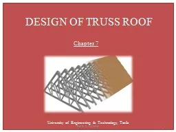
/
DESIGN OF TRUSS ROOF DESIGN OF TRUSS ROOF

DESIGN OF TRUSS ROOF - PowerPoint Presentation

mitsue-stanley
mitsue-stanley . @mitsue-stanley
Follow
415 views
Uploaded On 2017-11-08

DESIGN OF TRUSS ROOF - PPT Presentation

Chapter 7 University of Engineering amp Technology Taxila 1 Prof Dr Z A Siddiqi TABLE OF FORCES There are three important points to be considered while calculating the member forces Panel load multiplied with unit load forces gives the member forces by the principle of superposition ID: 603535

load col unit wind col load wind unit member forces pwl prof force siddiqi combination due table maximum loads tension pww side

Share:

Link:

Embed:

Download Presentation from below link

Download Presentation The PPT/PDF document "DESIGN OF TRUSS ROOF" is the property of its rightful owner. Permission is granted to download and print the materials on this web site for personal, non-commercial use only, and to display it on your personal computer provided you do not modify the materials and that you retain all copyright notices contained in the materials. By downloading content from our website, you accept the terms of this agreement.


Presentation Transcript

Slide1

DESIGN OF TRUSS ROOF

Chapter 7

University of Engineering & Technology, Taxila

1

Prof Dr Z. A. SiddiqiSlide2

TABLE OF FORCES

There are three important points to be considered while calculating the member forces: Panel load multiplied with unit load forces gives the member forces by the principle of superposition.

According to this principle, which is applicable for elastic structures, if a unit load is applied on a truss and the force in any member is calculated as F;

then

if we apply another unit load simultaneously at the same point, the force in the member will be

2F.

2

Prof Dr Z. A. SiddiqiSlide3

Similarly, this member force will be

3F for

three unit loads or P

x F

if P

times unit loads are applied.

Effects of various types of loads are to be added while calculating member forces.

Vertical and inclined loads on the truss cannot be added directly because of different lines of action of each.

However, separate member forces due to vertical and inclined loads have the same direction (along the member longitudinal axis) and hence can be algebraically added together.

3

Prof Dr Z. A. SiddiqiSlide4

Probability of occurrence of various loads in a load combination and corresponding load factors (factor of safety) are also applied during these calculations.

In case only dead, live and wind loads are acting on a truss, following combinations may be investigated: 1. 1.2

D + 1.6

Lr + 0.65

W

(Wind effect is small and may be ignored especially suction is present throughout)

4

Prof Dr Z. A. SiddiqiSlide5

2. 1.2

D + 0.5Lr + 1.3

W  Wind towards the Right

Wind towards the left

3. 0.9

D

+ 1.3

W Wind towards the Right Wind towards the Left

For the roof design, the first (gravity) or second (wind) load combination is critical. It is to be noted that the downward wind load is to be considered in the second combination.

5

Prof Dr Z. A. SiddiqiSlide6

The third combination is critical for reversal of forces and hence is evaluated for upward wind pressures.

In case the wind load has two values, one downward and one upward, the downward value should be used for the second combination and the upward value should be used for the third combination. It would be unreasonable to include full wind and full snow (or live load) stresses together in a single combination.

6

Prof Dr Z. A. SiddiqiSlide7

Similarly, when the wind is blowing at its full strength, the live load intensity may be reduced.

The second combination reflects the condition when most severe windstorm is blowing and hence the live load intensity may be reduced to 0.5/ 1.6 or 0.31 times its maximum intensity, showing less probability of occurrence of

full live load together with wind.

The third combination represents an unoccupied building subjected to the heaviest wind.

7

Prof Dr Z. A. SiddiqiSlide8

The negative sign with the wind forces only indicates that the combination is critical when the wind is producing member forces opposite in sense to that produced by the dead loads.

The design forces may be calculated by entering the values into a Table of Forces as in Table 7.2. The first four columns of this table are directly taken from the unit load analysis of the truss while columns 5 to 9 are calculated using the first four columns and the algebraic values of the panel loads, already determined.

8

Prof Dr Z. A. SiddiqiSlide9

9

Prof Dr Z. A. Siddiqi

Member No.Unit gravity load member forceMember force due to

unit Wind load on hinge side

Member force due to unit wind load on roller side

(1.2PD+1.6P

L

) x

Col.2(1.2 PD + 0.5 PL) x Col.2+ 1.3 P

ww x Col.3

+ 1.3

P

wL x Col.4

(1.2 PD + 0.5 P

L

) x

Col.2

+ 1.3 P

ww

x Col.4

+ 1.3

P

wL

x Col.3

(

0.9 P

D

) x

Col.2

+ 1.3 P

ww

x Col.3

+ 1.3

P

wL

x Col.4(0.9 PD) x Col.2+1.3 P ww x Col.4+1.3 PwL x Col.3Maximum factored tension(Tu)Maximum factoredCompression (Pu)Remarks(1)(2)(3)(4)(5)(6)(7)(8)(9)(10)(11)(12)

Sample Table of ForcesSlide10

After getting the values in these columns, the maximum factored tension and compression may be found out and entered in the next two columns.

Usually tension is represented by positive sign and compression by a negative sign in columns 2 to 4 and hence maximum tension is defined as the maximum positive value and maximum compression as the minimum value (maximum negative answer) in columns 5 to 9.10Prof Dr Z. A. SiddiqiSlide11

The remarks column is used to describe the type of the member for design such as pure tension member, pure compression member, member under reversal of stresses and zero force member.

A computer spreadsheet may conveniently be used to construct such a table. The truss members may now be selected by using the procedure given in earlier chapters and connections may be designed by the methods outlined in the coming chapters.

11

Prof Dr Z. A. SiddiqiSlide12

Unit Gravity LoadsSlide13

13

Prof Dr Z. A. Siddiqi

Member No.Unit gravity load member forceMember force due to

unit Wind load on hinge side

Member force due to unit wind load on roller side

(1.2PD+1.6P

L

) x

Col.2

Maximum factored tension

(

T

u)

Maximum factored

Compression (

P

u

)

Remarks

(1)

(2)

(3)

(4)

(5)

(6)

(7)

(8)

(9)

(10)

(11)

(12)

Sample Table of ForcesSlide14

Unit Wind Load on Hinge SideSlide15

Unit Wind Load on Roller SideSlide16

If Panel wind load is negative = SuctionSlide17

P

ww

P

ww

= +

ve

(1.2P

D

+0.5P

L

) X COL. 2

+

1.3 P

WW

X COL. 3Slide18

P

ww

P

wl

P

ww

= +

ve

(1.2P

D

+0.5P

L

) X COL. 2

+

1.3 P

WW

X COL. 3

P

wl

= -

veSlide19

P

ww

P

wl

P

ww

= +

ve

P

wl

= -

ve

(1.2P

D

+0.5P

L

) X COL. 2

+

1.3 P

WW

X COL. 3

+

1.3 P

WL

X COL. 4

Load Combination in Column No 6Slide20

P

ww

P

wl

P

ww

= +

ve

P

wl

= -

ve

(1.2P

D

+0.5P

L

) X COL. 2

+

1.3 P

WW

X COL. 3

+

1.3 P

WL

X COL. 4Slide21

21

Prof Dr Z. A. Siddiqi

Member No.Unit gravity load member forceMember force due to

unit Wind load on hinge side

Member force due to unit wind load on roller side

(1.2PD+1.6P

L

) x

Col.2(1.2 PD + 0.5 PL) x Col.2+ 1.3 P

ww x Col.3

+ 1.3

P

wL x Col.4

Maximum factored tension

(

T

u

)

Maximum factored

Compression (

P

u

)

Remarks

(1)

(2)

(3)

(4)

(5)

(6)

(7)

(8)

(9)

(10)

(11)

(12)

Sample Table of ForcesSlide22

Pww= +

veP

wl = -ve(1.2PD+0.5PL) X COL. 2+

1.3 PWW X COL. 4+

1.3 PWL X COL. 3

P

ww

P

wl

Load Combination in Column No 7Slide23

23

Prof Dr Z. A. Siddiqi

Member No.Unit gravity load member forceMember force due to

unit Wind load on hinge side

Member force due to unit wind load on roller side

(1.2PD+1.6P

L

) x

Col.2(1.2 PD + 0.5 PL) x Col.2+ 1.3 P

ww x Col.3

+ 1.3

P

wL x Col.4

(1.2 PD + 0.5 P

L

) x

Col.2

+ 1.3 P

ww

x Col.4

+ 1.3

P

wL

x Col.3

Maximum factored tension

(

T

u

)

Maximum factored

Compression (

P

u

)

Remarks

(1)

(2)(3)(4)(5)(6)(7)(8)(9)(10)(11)(12)Sample Table of ForcesSlide24

P

ww

P

wl

P

ww

= -

ve

P

wl

= -

ve

(0.9P

D

) X COL. 2

+

1.3 P

WW

X COL. 3

+

1.3 P

WL

X COL. 4

Load Combination in Column No 8Slide25

25

Prof Dr Z. A. Siddiqi

Member No.Unit gravity load member forceMember force due to

unit Wind load on hinge side

Member force due to unit wind load on roller side

(1.2PD+1.6P

L

) x

Col.2(1.2 PD + 0.5 PL) x Col.2+ 1.3 P

ww x Col.3

+ 1.3

P

wL x Col.4

(1.2 PD + 0.5 P

L

) x

Col.2

+ 1.3 P

ww

x Col.4

+ 1.3

P

wL

x Col.3

(

0.9 P

D

) x

Col.2

+ 1.3 P

ww

x Col.3

+ 1.3

P

wL

x Col.4Maximum factored tension(Tu)Maximum factoredCompression (Pu)Remarks(1)(2)(3)(4)(5)(6)(7)(8)(9)(10)(11)(12)Sample Table of ForcesSlide26

Pww= -

veP

wl = -ve(0.9PD) X COL. 2+ 1.3 PWW

X COL. 4+ 1.3 PWL

X COL. 3

P

ww

P

wl

Load Combination in Column No 9Slide27

27

Prof Dr Z. A. Siddiqi

Member No.Unit gravity load member forceMember force due to

unit Wind load on hinge side

Member force due to unit wind load on roller side

(1.2PD+1.6P

L

) x

Col.2(1.2 PD + 0.5 PL) x Col.2+ 1.3 P

ww x Col.3

+ 1.3

P

wL x Col.4

(1.2 PD + 0.5 P

L

) x

Col.2

+ 1.3 P

ww

x Col.4

+ 1.3

P

wL

x Col.3

(

0.9 P

D

) x

Col.2

+ 1.3 P

ww

x Col.3

+ 1.3

P

wL

x Col.4(0.9 PD) x Col.2+1.3 P ww x Col.4+1.3 PwL x Col.3Maximum factored tension(Tu)Maximum factoredCompression (Pu)Remarks(1)(2)(3)(4)(5)(6)(7)(8)(9)(10)(11)(12)

Sample Table of ForcesSlide28

?Slide29

Assignment:

Draw the Table

of Forces for Your Data & find the Truss Member Forces.

Time Allowed: 1 week