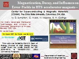
Mike Sumption M Majoros C Myers and EW Collings Center for Superconducting and Magnetic Materials MSE The Ohio State University This work was supported by the US Department of Energy Office of Science Division of High Energy Physics under Grant DESC0011721 ID: 783151
Download The PPT/PDF document "Modelling and Measurement of Magnetizati..." is the property of its rightful owner. Permission is granted to download and print the materials on this web site for personal, non-commercial use only, and to display it on your personal computer provided you do not modify the materials and that you retain all copyright notices contained in the materials. By downloading content from our website, you accept the terms of this agreement.
Slide1
Modelling and Measurement of Magnetization of YBCO CORC and Roebel Cables for Accelerators
Mike
Sumption, M. Majoros, C. Myers, and E.W. CollingsCenter for Superconducting and Magnetic Materials, MSE, The Ohio State University
This work was supported by the U.S. Department of Energy, Office of Science, Division of High Energy Physics, under Grant DE-SC0011721.
D. Van Der
Laan
Advanced
Conductor Technologies and University of Colorado
Slide2OSU Magnetization RigsMagnetization Measurement Facilities: A number of options are available, some systems better suited to given samples or given test requirements
Slide3MAG-0: 14 T, 2K-RT PPMS
Quantum Design Physical Property Measuring System (PPMS) equipped with a 14 T superconducting magnet and temperature control from 1.8 K to 400 K, can measure: M-H, AC susceptibility, AC transport, DC transport, Thermal conductivity, Hall effect, Heat capacity. Used to measure Nb
3Sn M-H loops and magnetizations, as well as those of Bi:2212 strand
Slide4MAG-1: 4.2 K, +- 12 T
Figure A6.2. Magnetization rig MAG-1, for samples larger than can be measured in the PPMS, but smaller than use for MAG-2. This is a susceptibility rig type magnetometer inside of a 12 T cryocooled magnet. Inside the 3” diameter room temperature bore is a varitemp dewar with a magnetization insert (b) side view, (c) face view. A current of up to 200 A can be applied to samples which are being measured for
M-H
.Magnetization rig MAG-1, for samples larger than can be measured in the PPMS, but smaller than use for MAG-2. This is a susceptibility rig type magnetometer inside of a 12 T cryocooled magnet. Inside the 3” diameter room temperature bore is a varitemp dewar with a magnetization insert (b) side view, (c) face view. A current of up to 200 A can be applied to samples which are being measured for M-H.
Slide5MAG-2
(d)
a
b
c
Cable Magnetization measuring facility (projected operational Fall 2015);
3 T coil (
Cryomagnetics
design and made),
NbTi
wound, 150 amperes, Inductance of
10
milliHenries
. Clear bore is 5.5 cm total length 30.48 cm.
Cryofab
dewar
and hang-down
assembly.
Drawing
of coils, homogeneity on-axis is +/- 5% over 15 cm
,
radial
field homogeneity.
Slide6MAG-3
M-H and AC Loss
device for 77 K measurements of YBCO, with typical sample shown above (YBCO CORC cable in this case). External-Field M-H and AC Loss is measured in the applied fields of copper wound solenoids and race-track coils of various sizes.A system of pick-up coils connected to a digital oscilloscope records the samples' M-H loops Used in this program for screening and as a comparison/calibration measurement at 77 K
Slide7Why the focus on Magnetization? – its b3 and its change for accelerator magnets
Slide8Magnetization Decay Suppression with Zr dopingMagnetization decay for coated conductors from UoH with (a) 2713-2: 0% Zr, (b) 2674-4: 7.5% Zr, (c) 2698-5: 25% New YBCO conductor with Zr pinning, University of HoustonMeasurement with PPMS
Slide9Measurements on CORC at 77 K
Slide10Striated measurement results 77 KStriations do significantly reduce lossSome factor from striation, some from
Ic loss
Slide11CORC Loss Striated vs non-straited
Slide12Magnetization – but loss?For the LHC NbTi dipoles ramping at about 7 mT/s AC loss is only a small contributor to cryogenic loadCould be larger for YBCO cables. For a YBCO cable carrying a current of 10 kA at 20 T the loss at 7 mT/s is estimated to be 200 mW/mFor an HTS insert of, say, 70 turns the winding dissipation would be 14 W/m -- more than double the LHC ring’s 4.5 K/1.8 K refrigeration capacityThis is a handle-able problem, but not of no interest
Slide13FEM Modelling
Initial approach
Model to start as model of one helix, then moving to multiplesTreat the SC film as distributedJc values are representative of 4 K, 0 T
Slide14Modelling Treatment – Average to composite Volume
SC, 1
mSubstrate, 50 m Composite, 250 m
M = CJcdMsc = msc/Vsc= CJcdLet Je=Jc/ffMcomp = Msc/Vcomp = Msc/(
Vsc*ff)=msc
J
cd
/
ff
=
m
sc
CJ
e
d
So we can treat the current as flowing through the whole composite and get a proper M
Penetration field,
B
p
=
CJ
c
d
So, only OK if re-normalization is in same dimension as d
Slide15Magnetization calculation for 1 strand CORC cable 4 K, Bean model
Slide16Comparison loss shape to model
AC loss of sample R3 at 50 Hz in liquid nitrogen bath (77 K)
FEM model prediction
Slide17SummaryVarious magnetization rigs are in operation and also commissioningUnder construction – 3 T, 4 K AC loss rig capable of 25 cm YBCO cable samplesMagnetization measurement, modelling, and comparison to accelerator targets underwayDrift measurements to look at changes in b3 underway – improvement seen with new superpower Zr doping