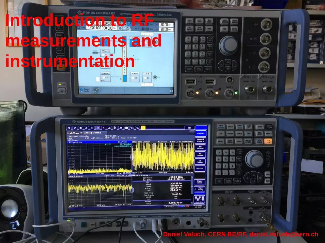
Daniel Valuch CERN BERF danielvaluchcernch Content RF power measurement Spectrum analyzers Vector network analyzers Document reference 2 3132018 RF power measurement Diode envelope detection ID: 1031589
Download Presentation The PPT/PDF document "Introduction to RF measurements and inst..." is the property of its rightful owner. Permission is granted to download and print the materials on this web site for personal, non-commercial use only, and to display it on your personal computer provided you do not modify the materials and that you retain all copyright notices contained in the materials. By downloading content from our website, you accept the terms of this agreement.
1. Introduction to RF measurements and instrumentationDaniel Valuch, CERN BE/RF, daniel.valuch@cern.ch
2. ContentRF power measurementSpectrum analyzersVector network analyzersDocument reference23/13/2018
3. RF power measurementDiode envelope detection: Most common, large dynamic range, suitable for constant signalsThermal: Very accurate, limited dynamic range, ideal for complex modulated signalsElectronic receivers: Most complex, suitable for fast, pulsed signalsIntroduction to RF measurements and instrumentationDaniel Valuch CERN BE/RF (daniel.Valuch@cern.ch)3Most popular methods to measure the RF power
4. RF power measurementHow to read specifications of a power sensorIntroduction to RF measurements and instrumentationDaniel Valuch CERN BE/RF (daniel.Valuch@cern.ch)4Frequency range:Diode sensors ~10MHzThermal sensors DCPulsed sensors 50-100MHzPower/dynamic range:Minimum and maximum power for your application. Values change typ. factor 1000+ between room temperature and superconducting stateExternal trigger and interface:Synchronized acquisition, USB interface, ethernet…
5. RF power measurementHow to use a RF power meterIntroduction to RF measurements and instrumentationDaniel Valuch CERN BE/RF (daniel.Valuch@cern.ch)51. Set the frequency2. Zero the offset3. Connect sensor to the signal source
6. RF power measurementIntroduction to RF measurements and instrumentationDaniel Valuch CERN BE/RF (daniel.Valuch@cern.ch)6Chose the desired measurement unitIf measuring through couplers/ attenuators etc. set-up the offset for direct reading of the source power value, instead of measured power value
7. RF power measurementSome comments:The reading is noisier at the bottom of the dynamic rangeThe power sensor really burns when overloaded (very costly to repair)Sensors have optimized dynamic range for type of measurements they do (very accurate, very fast, RMS…)Sensors and instruments need certain time to measure a data point, be careful with automationDecide what to buy based on how are you going to use the instrument: Table top, USB sensor, Ethernet sensor…Introduction to RF measurements and instrumentationDaniel Valuch CERN BE/RF (daniel.Valuch@cern.ch)7
8. Spectrum analyzerSpectrum analyser is a device, which measures frequency content of a signal.Introduction to RF measurements and instrumentationDaniel Valuch CERN BE/RF (daniel.Valuch@cern.ch)8
9. Spectrum analyser user interfaceIntroduction to RF measurements and instrumentationDaniel Valuch CERN BE/RF (daniel.Valuch@cern.ch)9FrequencyAmplitude
10. Spectrum analyser user interfaceIntroduction to RF measurements and instrumentationDaniel Valuch CERN BE/RF (daniel.Valuch@cern.ch)10StartX axis, frequency span: SpanCenter frequency: CenterStop
11. Spectrum analyser user interfaceIntroduction to RF measurements and instrumentationDaniel Valuch CERN BE/RF (daniel.Valuch@cern.ch)11Y axis, 1 square (/division)Y axis, full scale 10 squareSet by: Amplitude/scale
12. Spectrum analyser user interfaceIntroduction to RF measurements and instrumentationDaniel Valuch CERN BE/RF (daniel.Valuch@cern.ch)12Other important settings
13. Spectrum analyser user interfaceIntroduction to RF measurements and instrumentationDaniel Valuch CERN BE/RF (daniel.Valuch@cern.ch)13
14. Spectrum analyzer user interfaceIntroduction to RF measurements and instrumentationDaniel Valuch CERN BE/RF (daniel.Valuch@cern.ch)14
15. Spectrum analyzer user interfaceIntroduction to RF measurements and instrumentationDaniel Valuch CERN BE/RF (daniel.Valuch@cern.ch)15Screen + Soft keysFrequency and amplitudeMarkers and advancedRF input
16. Spectrum analyser user interfaceIntroduction to RF measurements and instrumentationDaniel Valuch CERN BE/RF (daniel.Valuch@cern.ch)16
17. Spectrum analyser user interfaceIntroduction to RF measurements and instrumentationDaniel Valuch CERN BE/RF (daniel.Valuch@cern.ch)17Screen + Soft keysFrequency and amplitudeMarkers and advancedRF and IF inputs
18. IF detector bandwidth – resolution bandwidthIntroduction to RF measurements and instrumentationDaniel Valuch CERN BE/RF (daniel.Valuch@cern.ch)18Resolution bandwidthSweep timeReceiver signal bandwidth prior the power detectorIF/resolution bandwidth defines the measurement noise floor AND how close two different signals can be in order to still distinguish themDifferent signalsNoise floor
19. IF detector bandwidth – resolution bandwidthIntroduction to RF measurements and instrumentationDaniel Valuch CERN BE/RF (daniel.Valuch@cern.ch)19Receiver signal bandwidth prior the power detectorIF/resolution bandwidth defines the measurement noise floor AND how close two different signals can be in order to still distinguish them
20. Real time spectrum analyzerIntroduction to RF measurements and instrumentationDaniel Valuch CERN BE/RF (daniel.Valuch@cern.ch)20
21. Signal demodulation by s.a.Introduction to RF measurements and instrumentationDaniel Valuch CERN BE/RF (daniel.Valuch@cern.ch)21
22. Modern spectrum analysersIntroduction to RF measurements and instrumentationDaniel Valuch CERN BE/RF (daniel.Valuch@cern.ch)22
23. Vector network analyserVector network analyser is a device, which excites a RF network and measures a response from its ports. All signals are measured as phasors.Introduction to RF measurements and instrumentationDaniel Valuch CERN BE/RF (daniel.Valuch@cern.ch)23If we know RFL and FWDwe can calculate:VSWRS-parameters S11, S12Reflection coefficient GImpedance R+jXAdmitance Y+jBInput matchingIf we know TRN and FWDwe can calculate:Gain, attenuationS-parameters S21, S22Transmission coefficient TGroup delayPhase shift
24. Vector network analyserIntroduction to RF measurements and instrumentationDaniel Valuch CERN BE/RF (daniel.Valuch@cern.ch)24
25. Vector network analyserHow does the VNA measure?Send signal from port 1 and measure the response at port 1 and port 2Introduction to RF measurements and instrumentationDaniel Valuch CERN BE/RF (daniel.Valuch@cern.ch)25
26. Vector network analyserHow does the VNA measure?Send signal from port 1 and measure response at port 1 and port 2Introduction to RF measurements and instrumentationDaniel Valuch CERN BE/RF (daniel.Valuch@cern.ch)26S11=A-/R
27. Vector network analyserHow does the VNA measure?Send signal from port 1 and measure response at port 1 and port 2Introduction to RF measurements and instrumentationDaniel Valuch CERN BE/RF (daniel.Valuch@cern.ch)27S21=B-/A+
28. VNA user interfaceIntroduction to RF measurements and instrumentationDaniel Valuch CERN BE/RF (daniel.Valuch@cern.ch)28X Axis, typ. FrequencyStart/stopCenter/spanMenu bar
29. VNA user interfaceIntroduction to RF measurements and instrumentationDaniel Valuch CERN BE/RF (daniel.Valuch@cern.ch)29Y axis, measured parameter
30. VNA user interfaceIntroduction to RF measurements and instrumentationDaniel Valuch CERN BE/RF (daniel.Valuch@cern.ch)30Instrument status, calibration, reference etc.
31. VNA user interfaceIntroduction to RF measurements and instrumentationDaniel Valuch CERN BE/RF (daniel.Valuch@cern.ch)31Calculation of a derived parameter using the measured trace
32. Setting up process…Introduction to RF measurements and instrumentationDaniel Valuch CERN BE/RF (daniel.Valuch@cern.ch)32Super important for high-Q device measurements
33. Few notes on IF bandwidthVNA uses a super-heterodyne receivers to measure the RF signalsSame noise handling procedures as for the spectrum analyser applyIntroduction to RF measurements and instrumentationDaniel Valuch CERN BE/RF (daniel.Valuch@cern.ch)33
34. IF (detector) bandwidthBandpass filter measurement, fc=1GHzIntroduction to RF measurements and instrumentationDaniel Valuch CERN BE/RF (daniel.Valuch@cern.ch)34IF bandwidth 100kHz
35. IF (detector) bandwidthBandpass filter measurement, fc=1GHzIntroduction to RF measurements and instrumentationDaniel Valuch CERN BE/RF (daniel.Valuch@cern.ch)35IF bandwidth 10kHz
36. IF (detector) bandwidthBandpass filter measurement, fc=1GHzIntroduction to RF measurements and instrumentationDaniel Valuch CERN BE/RF (daniel.Valuch@cern.ch)36IF bandwidth 1kHz
37. IF (detector) bandwidthBandpass filter measurement, fc=1GHzIntroduction to RF measurements and instrumentationDaniel Valuch CERN BE/RF (daniel.Valuch@cern.ch)37IF bandwidth 100Hz
38. IF (detector) bandwidthBandpass filter measurement, fc=1GHzIntroduction to RF measurements and instrumentationDaniel Valuch CERN BE/RF (daniel.Valuch@cern.ch)38IF bandwidth 10HzNoise floor for IFBW=100kHzNoise floor for IFBW=10Hz
39. IF (detector) bandwidthBandpass filter measurement, fc=1GHzIntroduction to RF measurements and instrumentationDaniel Valuch CERN BE/RF (daniel.Valuch@cern.ch)39IF bandwidth 10HzPlus averaging
40. Measurement errors and calibrationThe instrument always shows some curves……but in 99% cases this is not what you want to measureIntroduction to RF measurements and instrumentationDaniel Valuch CERN BE/RF (daniel.Valuch@cern.ch)40verydemotivational.com
41. Measurement errors and calibration“Hello Daniel, this is Nikolai. We are trying to measure the 1.3GHz superconducting cavity but the instrument shows something strange…”Introduction to RF measurements and instrumentationDaniel Valuch CERN BE/RF (daniel.Valuch@cern.ch)41
42. Measurement errors and calibrationWe work in the RF domainThe instrument measures our DUT…but also everything around (cables, connectors, adapters, spurious reflections etc.)…and the instrument is sensitive to temporal alignment of the signals as well…finally the instrument also measures himselfIntroduction to RF measurements and instrumentationDaniel Valuch CERN BE/RF (daniel.Valuch@cern.ch)42
43. Measurement errors and calibrationAll networks which connect DUT to the instrument introduce static systematic errorsWe can measure them and mathematically de-embed them from the measurementThis process is called CalibrationIntroduction to RF measurements and instrumentationDaniel Valuch CERN BE/RF (daniel.Valuch@cern.ch)43
44. Measurement errors and calibrationAll networks which connect DUT to the instrument introduce static systematic errorsWe can measure them and mathematically de-embed them from the measurementThis process is called CalibrationIntroduction to RF measurements and instrumentationDaniel Valuch CERN BE/RF (daniel.Valuch@cern.ch)44
45. Measurement errors and calibrationDirectional coupler measurement without and with full calibrationIntroduction to RF measurements and instrumentationDaniel Valuch CERN BE/RF (daniel.Valuch@cern.ch)45Without calibrationFull calibration
46. Calibration process3 standards: Open, Short, Load + ThruIntroduction to RF measurements and instrumentationDaniel Valuch CERN BE/RF (daniel.Valuch@cern.ch)46
47. Thank you for your attentionIntroduction to RF measurements and instrumentationDaniel Valuch CERN BE/RF (daniel.Valuch@cern.ch)47Thank you for your attentionAfter the break: hands on part