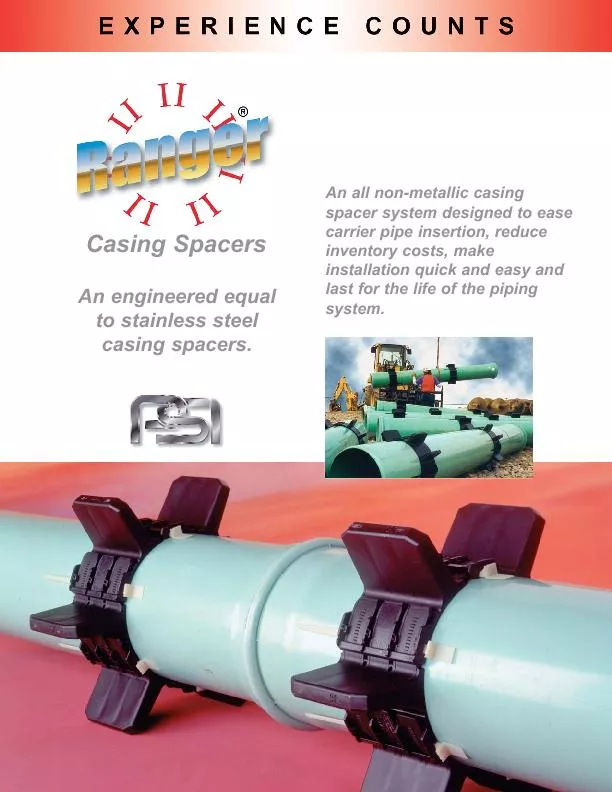
/
An all non-metallic casing spacer system designed to easesystem. 
... An all non-metallic casing spacer system designed to easesystem. 
...

An all non-metallic casing spacer system designed to easesystem. ... - PDF document

myesha-ticknor
myesha-ticknor . @myesha-ticknor
Follow
392 views
Uploaded On 2016-09-24

An all non-metallic casing spacer system designed to easesystem. ... - PPT Presentation

Casing Spacers An engineered equalto stainless steelcasing spacers Typical Installation Based on 20 ID: 470166

Casing Spacers An engineered equalto stainless

Share:

Link:

Embed:

Download Presentation from below link

Download Pdf The PPT/PDF document "An all non-metallic casing spacer system..." is the property of its rightful owner. Permission is granted to download and print the materials on this web site for personal, non-commercial use only, and to display it on your personal computer provided you do not modify the materials and that you retain all copyright notices contained in the materials. By downloading content from our website, you accept the terms of this agreement.


Presentation Transcript

An all non-metallic casing spacer system designed to easesystem. Casing Spacers An engineered equalto stainless steelcasing spacers. Typical Installation Based on 20 (6.1M) carrier pipe segments in a casingof not more than 300 (91.5M). Consult PSI for longercasings and for concrete pipe. Use 2 spacers/length ofpipe for 13 (4.0M) sewer pipe segments. 8 Max.2 Max.2 Max.8 Max. PSI Model CŽ or Features € All non-metallic. No nuts, bolts, washers or any other metal parts to corrode(955mm) in diameter.€ Easy assembly. Simply slide the segments together and€ Wide variety of runner heights to allow numerous options€ Will accommodate small conduit attachment for communications€ Excellent compressive strength, 3,000 psi (211 kg/square cm)€ 800 Volts/Mil. Dielectric Strength.€ Wide temperature range, -22º to +212º F. (-30º to +100º C.) € Low coefficient of friction for ease Field Installation, Midi segments on ductile iron pipe. Weight Comparison9.05Ž x 17.25Ž CR Application Ranger II Advantage Installer and Shipping Costs Ranger II Model S8G-2Non-Metallic StainlessSteel2.79 lbs. 15 lbs. Component Parts - Installation Separate segments are connected byinserting the buckles into slots on the Slots accept buckles andaround pipe in preparation for the segments together afterinstallation on pipe. Channels Slot accepts Slide-Lock. variety of heights to allow for close and lock the segments together.will cinch the segments together for Installation Tips € As with any installation process, it isimportant to wear appropriate eyeand personal protection. This iseven more important if installationCasing Spacer segmentsment while awaiting installation in€ During the installation process, no€ Under hot installation conditions, it isature prior to assembly. Weight and Spacing Guidelines(Maximum Distance Between Casing Spacer.) Skid Height 1.50Ž (38mm) to 1.97Ž (50mm)8 (Feet)Skid Height 2.56Ž (65mm) to 3.54Ž (90mm)6 (Feet)Skid Height 3.94Ž (100mm) and up5 (Feet) MICROMINIMIDIMEDIMAXISkid Height 1.50Ž (38mm) to 1.97Ž (50mm)175 lb.500 lb.1,250 lb.3,300 lb.5,000 lb.Skid Height 2.56Ž (65mm) to 2.95Ž (75mm)135 lb.400 lb.1,000 lb.2,600 lb.4,000 lb.Skid Height 3.54Ž(90mm) to 3.94Ž (100mm)120 lb.350 lb.875 lb.2,300 lb.3,500 lb.Skid Height 4.92Ž (125mm) to 5.91Ž (150mm) 250 lb.625 lb.1,650 lb.2,500 lb.Skid Height 6.89Ž (175mm)550 lb.1,400 lb.2,300 lb. 1.501.751.972.562.953.54 3.94 4.925.916.89(38)(44)(50)(65)(75) (90) (100) (125) (150)(175) Installed On Various Pipe Types, Such As: PVC Water, PVC Sewer, HDPESteel, Ductile Iron...etc. Band Width = 8.86Ž (225mm) Carrier Pipe O.D. RangeNo. ofRunner Height OptionsInches (mm)SegmentsInches (mm) 25.98 to 30.79 (660 to 782)630.79 to 37.60 (782 to 955)71.501.972.562.953.543.944.925.916.89(38)(50)(65)(75)(90)(100)(125)(150)(175) Band Width = 2.13Ž (54mm) Carrier Pipe O.D. RangeNo. ofRunner Height OptionsInches (mm)SegmentsInches (mm) 0.83 to 1.14 (21 to 29)31.14 to 1.54 (29 to 39)41.54 to 1.85 (39 to 47)51.501.972.562.953.543.941.85 to 2.24 (47 to 57)6(38)(50)(65)(75)(90)(100)2.24 to 2.48 (57 to 63)72.48 to 3.07 (63 to 78)8 Band Width = 3.15Ž (80mm) Carrier Pipe O.D. RangeNo. ofRunner Height OptionsInches (mm)SegmentsInches (mm) 2.48 to 3.07 (63 to 78)43.07 to 3.86 (78 to 98)53.86 to 4.49 (98 to 114)6 1.501.972.562.953.543.944.924.49 to 5.51 (114 to 140)7 (38)(50)(65)(75)(90)(100)(125) Band Width = 5.12Ž (130mm) Carrier Pipe O.D. RangeNo. ofRunner Height OptionsInches (mm)SegmentsInches (mm) 5.51 to 6.89 (140 to 175)46.89 to 8.70 (175 to 221)58.70 to 10.31 (221 to 262)61.501.75 1.972.562.953.543.944.925.916.8910.31 to 12.87 (262 to 327)7(38)(44)(50)(65)(75)(90)(100)(125)(150)(175)12.87 to 14.41 (327 to 366)814.41 to 16.65 (366 to 423)10 Page 4 Note: Detailed Ranger IIcasing spacers weight & spacing guidelines on page 3. Band Width = 6.87Ž (174 mm) Carrier Pipe O.D. RangeNo. ofRunner Height OptionsInches (mm)SegmentsInches (mm) 16.77 to 21.22 (426 to 539)421.22 to 25.98 (539 to 660)51.501.972.562.953.543.944.925.916.89(38)(50)(65)(75)(90)(100)(125)(150)(175) Verify that Slide-Locks match segment size by checking to ensure the segment name (Mini) matches thename molded on the bottom of the Slide-Lock. Note: Micro & Mini segments both use the Mini Slide-Lock. Verify that Slide-Locks match segment size by checking to ensureof the Slide-Lock. Note: Micro & Mini segments both use the Mini Verify that Slide-Locks match segment size by checking to ensure Verify that Slide-Locks match segment size by checking to ensureof the Slide-Lock. Note: Medi & Maxi segments both use the Maxi Verify that Slide-Locks match segment size by checking to ensureof the Slide-Lock. Note: Medi & Maxi segments both use the Maxi Size your Installation Application All Ranger II® Casing Spacers require more than one segment to complete a spacer. In addition, all Ranger II CasingSpacers are available with a number of different runner height options which are used to guarantee clearance of theadjustments. Following are examples on how to size Ranger II Casing Spacers for various applications. DetailedRanger IIcasing spacers weight & spacing guidelines on page 3. For exact centering and adjusting for grade elevation changes contact PSI. ExamplesCentered & Restrained with Equal Length Runners Find carrier pipe O.D. (21.60Ž) from adjacent chart and choose the proper size and number of segments.One spacer would require 5 - Medi segments.Casing I.D.35.25ŽLess Carrier Pipe O.D.-21.60Ž Less Space Allowance-1.00Ž Divide this number (12.65Ž) by 2 to obtain the total maximum runner height = 6.325ŽUse 5 - Medi (150) segments with runner heights of 5.91Ž. This combination will restrain the pipe from flotation within the casing pipe byThis will center the carrier pipe within approximately 0.9Ž of exact center. To Clear the Bell (Clear Bell)Bell O.D.28.63ŽAdd 0.8Ž Clearance+0.80Ž Less Barrel O.D.-21.60Ž Divide this number (7.83Ž) by 2 to obtain the minimum runner height to clear the bell = 3.92Ž Medi (100) segments with runner heights of 3.94Ž. Contact PSI (800-423-2410, 713-747-6948 or info@psipsi.com)For Sizing Applications to Exactly Center or Adjust for Grade Elevation Changes.Sizing and Quotation Program, Visit www.ranger2.com Please contact PSI if you are uncertain of the fit for a particular application. Standard To O.D.Casing PipeI.D.Bell O.D. Non-Metallic Casing Spacer & End Seal Specification for Carrier Pipe to 37.60 O.D. Molded non-metallic technology enables Ranger II® casing spacers to replace exisiting specified stainless steel casing spacers.A. Casing SpacersUpon completion of the installation of the steel pipe encasement, the con-tractor shall furnish and install a Ranger II® boltless casing spacer on thecarrier pipe as described below.Casing spacers shall be spaced a maximum of eight (8) feet apart alongthe length of the carrier pipe with one casing spacer within two (2) feet ofeach side of a pipe joint and the rest evenly spaced. Wood skids are not an acceptable method of1. Casing spacers shall be all non-metallic (polypropylene), molded in segments for fieldassembly without any special tools. Spacer segments shall be secured around carrier pipe byinsertion of a Slide-Lock. The casing spacer polymer shall contain ultraviolet inhibitors andshall have a minimum compressive strength of 3,000 psi, an 800 Volts/mil dielectric strengthand impact strength of 1.5 ft-lbs./inch. Each casing spacer shall have full length, integrally2. Spacers shall be at least as wide as listed below. Carrier Pipe DiameterRanger IIWidthInches (mm) 0.83 to 3.07Ž (21 to 78)Micro2.13Ž (54)2.48 to 5.51Ž (63 to 140)Mini3.15Ž (80)5.51 to 16.65Ž (140 to 423)Midi5.12Ž (130)16.77 to 25.98Ž (426 to 660)Medi6.87Ž (174)25.98 to 37.60Ž (660 to 955)Maxi8.86Ž (225)3. The casing spacers shall be the boltless/all non-metallic PSI Ranger II® Casing Spacers as manufac-tured by Pipeline Seal and Insulator, Inc., Houston,Texas.After insertion of the carrier pipe into the casing, the ends ofthe casing shall be closed by installing 1/8Ž thick syntheticby Pipeline Seal and Insulator, Inc., Houston, Texas.Each casing spacer and end seal shall be manufactured at Registration shall be provided with material submittal.WarrantyAll products are warranted against failure caused by manufacturing defects for a period of one year.replaced without charge. The above warranty is made in lieu of, and we disclaim, any and all otherwarranties, expressed or implied, including the warranties of merchantability and fitness for a particu-lar purpose, and buyer agrees to accept the products without any such warranties. We hereby dis-claim any obligation or liability for consequential damages, labor costs or any other claims or liabili-ties of any kind whatsoever. Page 6 Band/Runner SegmentsUV resistant polypropyleneSpecificationsValueCompressive Strength3,000 psi(211 kg/sq. cm) Temperature-22°F. to +212°F. Impact Strength1.5 ft. lb/in. Dielectric Strength800 Volts/mil. min. ColorBlack Liner None Basic Installation Procedure casing spac-segments and Slide-Locks. previous step until all segmentsare put together. You are nowspacer around the pipe. 7A. To tighten Ranger II casingspacer, back the Slide-Lock com-push segments together by hand.spacer assembly tightens down on pletely into segment by lightly tap-slots. 8. Continue steps 7A and 7B untilRanger II Casing Spacer is secureagainst carrier pipe making certain 5. Align the buckles and lock intoplace. Take the final Slide-Lockslots. ening by lightly tapping each Slide-hammer. 2. Take the segments and alignof the way into the slots. tips out the end of the segment. Always Wear and Use Safety Equipment! Pipeline Seal and Insulator, Inc.6525 Goforth Street, Houston, TX 77021Telephone: 713-747-6948, Facsimile: 713-747-6029Toll Free: 800-423-2410www.pipelineseal.com, www.ranger2.com, e-mail: info@psipsi.com©2008, Pipeline Seal and Insulator, Inc.PSI-RII-11/08easy installation.Model WŽ Wrap AroundSpecifically designed forexisting installations.surfaces together.Available for all carrier/cas-ing differential. Model SŽ Standard Pull-onlong life and easy installation, the high-for ANSI steel pipe specifications.Band locating ribs are on the outside, Model FWŽ Fire Resistantfire retention. They are appli-dikes in tank farms, fire walls (up to 20 psig [40 feet of End Seals PSI Metallic Casing Spacers(Painted, Coated or Stainless)For pushes over 300ft long or for extrause of PSI Metallic Casing Spacers. Consultdetails. Literature and specifications availablefor metallic spacers at www.pipelineseal.com Compare Ranger IIspacer pricing versus olderstainless steel technology. To Order Ranger II Casing Spacers Please Indicate: 1.Total Quantity of Spacers2. Model No. (Ranger II)3. Carrier Pipe O.D.4. Casing Pipe I.D.5. Bell O.D.6. Runner ConfigurationS = Standard Bell Clearance Only7. Segment Size (Micro, Mini, Midi, Medior Maxi)8. Runner Lengths9. No. of Segments/Spacer10. Contact your local distributor or PSI