/
L-10(M-9) torque and rotational inertia L-10(M-9) torque and rotational inertia

L-10(M-9) torque and rotational inertia - PowerPoint Presentation

myesha-ticknor
myesha-ticknor . @myesha-ticknor
Follow
378 views
Uploaded On 2017-09-08

L-10(M-9) torque and rotational inertia - PPT Presentation

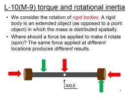
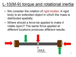
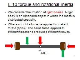
We consider the rotation of rigid bodies A rigid body is an extended object as opposed to a point object in which the mass is distributed spatially Where should a force be applied to make it rotate ID: 586178

object torque force rotational torque object rotational force inertia axis center rotate net point applied stable mass wrench gravity

Share:

Link:

Embed:

Download Presentation from below link

Download Presentation The PPT/PDF document "L-10(M-9) torque and rotational inertia" is the property of its rightful owner. Permission is granted to download and print the materials on this web site for personal, non-commercial use only, and to display it on your personal computer provided you do not modify the materials and that you retain all copyright notices contained in the materials. By downloading content from our website, you accept the terms of this agreement.


Presentation Transcript

Slide1

L-10(M-9) torque and rotational inertia

We consider the rotation of rigid bodies. A rigid body is an extended object (as opposed to a point object) in which the mass is distributed spatially.Where should a force be applied to make it rotate?The same force applied at different locations produces different results.

1

AXLESlide2

TORQUE – Greek letter tau

t To make an object rotate, a force must be applied in the right place.the combination of force and point of application is called TORQUEThe

lever arm L is the distance from the axis of rotation to the point where the force is appliedIf the line of action of F passes through the axis of rotation, it produces no torque.

Force, F

lever

arm:

L

Axis

2Slide3

force F in

Newtons,

Nlever arm L in meters, m

Torque t in units of N mTorque: t (Greek tau) Torque = force (F) x lever arm (L)t = F L

3Slide4

Torque example

F

L

What is the torque on a bolt

applied with a wrench that

has a lever arm: L= 20 cm

with a force: F = 30 N?

Solution:

t

=

F

L = 30 N  0.2 m = 6 N m

For the same force, you get more torquewith a bigger wrench  the job is easier!

4Slide5

Torque wrench

5

A torque wrench is a wrench that applies

a calibrated torque to a bolt.It prevents a bolt from being over-tightenedand possibly breaking.Slide6

Homer attempts to straighten out the leaning tower of Pisa

fulcrum

lever

6Slide7

Net Force = 0 , Net Torque

≠ 0

10 N

10 N

> The net force = 0, since the forces are applied in

opposite directions so it will not accelerate.

> However, together these forces will make the rod

rotate in the clockwise direction.

7Slide8

Net torque = 0, net force ≠ 0

The rod will accelerate upward under these

two forces, but will not rotate.

8Slide9

Balancing torques

10 N

20 N

1 m

0.5 m

Left torque = 10 N x 1 m = 10 n

m

counterclockwise

Right torque = 20 N x 0.5 m = 10 N

m

clockwise

9Slide10

Equilibrium

To ensure that an object does not accelerate or rotate two conditions must be met: net force = 0 net torque = 0

this results in the practical 4-1 “ladder rule”

10Slide11

When is an object stable?

If you can tip it over a bit and it doesn’t fallThe object may wobble a bit but it eventually stops and settles down to its upright position.

A thinner object is

easier to topple

An object that is thicker

at its base is more stable

11Slide12

Why do tall objects tend to fall over

Every object has a special point called the center of gravity (CG). The CG is usually in the center of the object.if the center of gravity is supported, the object will not fall over.

The lower the CG the more stable an object is. stable  not easy to knock over!

12Slide13

Condition for stability

If the CG is above

the

edge of the table, the objectwill not fall off.

CG

13Slide14

Why makes an object tip over?

For the wide object, the dashed line extending from the CG down is to the left of the point of contact; the torque due to the weight tends to rotate the object counterclockwiseFor the narrow object, the dashed line extending from the CG down is to the right of the point of contact, the torque due to the weight tends to rotate the object clockwise.

14

STABLE

UNSTABLE

D

D

CG

CGSlide15

Stable structures

Structures are

wider at their

base to lower their

center of gravity

15Slide16

If the center of gravity

is supported, the blocks

do not fall over

Playing with blocks

CG

16Slide17

Coin Stack

17Slide18

As more stuff is loaded into a semi, its center of gravity moves upward, making it susceptible to tipping over in high winds.

High Profile Vehicles

wind

18Slide19

Rotational Inertia

(moment of inertia) symbol IA rigid body is characterized by a parameter called

its rotational inertiaThe rotational inertia of a RB depends on how its mass is distributed relative to the axis of rotationThe rotational inertia of a RB is a parameter that is analogous to inertia (mass) for a non-extended object For a RB, the rotational inertia determines how much torque is needed to produce a certain amount of rotational acceleration (spin).

19Slide20

rotational inertia examples

Rods of equal mass m and length L

axis through center

axis through end

20

The rod with the axis through the end requires more torque to get it rotating.Slide21

How fast does it spin?

For spinning or rotational motion, the rotational inertia of an object plays the same role as ordinary mass for simple motionFor a given amount of torque applied to an object, its rotational inertia determines its rotational acceleration  the smaller the rotational inertia, the bigger the rotational acceleration

21Slide22

Big rotational

inertia

Small rotational

inertia

Same

torque, different rotational

inertia

spins

slow

spins

fast

22

L = R

F = mg

t =

F L = (mg) R