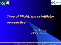
scintillator perspective Paul Lecoq CERN Geneva Where is the limit Philips and Siemens TOF PET achieve 550 to 650ps timing resolution About 9cm localization along ID: 558777
Download Presentation The PPT/PDF document "Time of Flight: the" is the property of its rightful owner. Permission is granted to download and print the materials on this web site for personal, non-commercial use only, and to display it on your personal computer provided you do not modify the materials and that you retain all copyright notices contained in the materials. By downloading content from our website, you accept the terms of this agreement.
Slide1
Time of Flight: the scintillator perspective
Paul Lecoq
CERN, GenevaSlide2
Where is the limit?
Philips and Siemens TOF PET
achieve
550 to 650ps timing
resolution
About 9cm
localization
along
the LOR
Can
we
approach
the
limit
of 100ps (1.5cm)?
Can
scintillators
satisfy
this
goal?Slide3
For the scintillator the important parameters are
Time structure of the pulse
Light
yield
Light transport affecting pulse shape, photon statistics and LY
Timing
parameters
decay
time of
the
fast
component
Photodetector
excess
noise factor
number
of
photoelectrons generated by the fast component
General
assumption
,
based
on
Hyman
theorySlide4
Light output: LYSO example
Statistics
on about 1000 LYSO pixels 2x2x20mm
3
produced by CPI for the ClearPEM-Sonic project (CERIMED)
Mean
value = 18615 ph/MeV
For 511
KeV
and 25%QE: 2378
phe
Assuming
ENF= 1.1
Nphe
/ENF ≈ 2200
pheSlide5
t
= 40 ns
N
phe
t
= 40 ns
N
phe
N
phe
N
phe
Statistical limit on timing resolution
W(Q,t
) is the time interval distribution between photoelectrons
= the probability
density that the interval between event Q-1 and event Q is
t
=
time resolution when the signal is triggered on the
Q
th
photoelectron
LSO
N
phe
=
2200Slide6
Light generation
Rare Earth
4f
5dSlide7
Rise time is as important as decay time
Rise timeSlide8
Photon counting approach
LYSO, 2200pe
detected
,
t
d
=40ns
t
r=0ns
t
r=0.2ns
tr=0.5ns
t
r
=1nsSlide9
Cross-Luminescent crystals (very
fast
,
low
LY)BaF2 (1400ph/MeV) but 600ps decay time produces more photons in the first ns (1100) than
LSO (670)!Direct bandgap
semiconductors S. Derenzo, SCINT2001Sub-ns band-to-band
recombination in ZnO, CuI,PbI2, HgI
2NanocrystalsBright and sub-ns
emission due to quantum confinement
Faster
than Ce3+?Intrinsic limit
at 17ns
Pr
3+
Pr
3+
5d-4f transition
is
always
1.55eV
higher
than
for Ce
3+Slide10
Material
Density (g/cm
3
)
Radiation length X
0
(cm)
Refraction index n
Critical angle
Fondamental absorption (nm)
Cerenkov
threshold energy for
e
(
KeV
)
Recoil
e
range
a
bove
C threshold (
m
m)
#
C photons / 511KeV
g
ray
*
PbWO
4
8.28
0.89
2.2
63°
370
63
513
21
LSO:Ce
7.4
1.14
1.82
57°
190
101
527
15
LuAG:Ce
6.73
1.41
1.84
57°
177
97
582
22
LuAP:Ce
8.34
1.1
1.95
59°
146
84
487
28
Ultimately
fast
using
Cerenkov
emission
?
Even
low
enegy
g
ray
produce
Cerenkov
emission
in dense,
high
n
materials
This emission is instantaneous with a 1/l2 spectrum
*
Low
wavelength
cut-off
set
at
250nm for
calculations
on LSO,
LuAG
and
LuAP
Ce absorption bands
subtracted
from
Cerenkov
transparency
windowSlide11
22Na
PMT left (2150V)
PMT right (1500V)
LuAG
2013 (
undoped
-> shows no scintillation)
LSO 1121
8
cm
8
cm
Crystals wrapped on
5 sides with
teflon
.
Scope
Coincidence:
Th_left
=-4mV,
th_right
=-500mV
CFD
LuAG
Cerenkov
/LYSO Scintillation
coincidence
measurement
FWHM=374ps
LuAG
=259ps
FWHM=650ps
LuAG
=587psSlide12
Light Transport-49° <
θ
< 49°
Fast
forward detection 17.2%131° < θ < 229°
Delayed back detection
17.2%57° < θ < 123° Fast escape on the sides 54.5% 49° < θ
< 57° and 123° < θ < 131°
infinite bouncing 11.1%
For a 2x2x20 mm
3
LSO
crystal
Maximum time
spread
related to difference in travel path
is
424
ps
peak
to
peak
≈
162
ps
FWHMSlide13
Photonic crystals to improve light extraction
Periodic
medium
allowing
to couple light propagation modes
inside
and
outside
the
crystal
M.
Kronberger
, E.
Auffray
, P. Lecoq, Probing the concept of Photonics Crystals on Scintillating Materials
TNS on
Nucl
. Sc. Vol.55, Nb3, June 2008,
p
. 1102-1106
24%
34%Slide14
LuAP
Light gain
2.1
LYSO
Light gain
2.08
BGO
Light gain
2.11
LuAG:Ce
Light gain
1.92
Expected
Light Output Gain
for
different
crystals
Litrani
+ CAMFR simulationSlide15
How does the PhC work?
Section of the plane crystal- air interface: (EM –
fieldplot
)
Crystal- air interface with
PhC
grating:
θ
>
θ
c
Total Reflection at the interface
Extracted Mode
θ
>
θ
c
Diffracted modes interfere constructively in the
PhC
- grating and are therefore able to escape the CrystalSlide16
PhC fabricationNano
Lithography
PhC
is produced in cooperation with the INL (
Institut des Nanotechnologies de Lyon) Three step approach:Sputter deposition of an auxiliary layer
Electron beam lithography (EBL)
Reactive ion etching (RIE)
RAITH® lithography kit:Slide17
PhC fabrication
Reactive Ion Etching (RIE)
Chemically reactive plasma removes Si
3
N4 not covered by the resist
Change the composition of the reactive plasma to remove the resist (PMMA) without etching the Si
3N4
x
z
y
Scintillator
ITO
Si
3
N
4
a
Hole depth:
300nm
h
ole diameter:
200nm
x
z
y
Scintillator
ITO
Si
3
N
4
Ion Bombardment
PMMA ResistSlide18
PhC fabrication
Results
Scanning Electron Images:
a = 340nm
D = 200nmSlide19
Use larger LYSO crystal: 10x10mm2 to
avoid
edge
effects6 different patches (2.6mm x 1.2mm) and 1 (1.2mm x 0.3mm) of different PhC
patterns
PhC first results
0°
45°
PreliminarySlide20
PhC improves light extraction eficiency
But
also
collimation of the
extracted lightSlide21
ConclusionsTiming
resolution
improves
with lower thresholdUltimate resolution
implies single photon
countingHigh light yield is mandatory100’000ph/MeV achievable with scintillatorsShort
decay time15-20ns is the
limit for bright scintillators (LaBr
3)
1ns achievable but with poor LY
Crossluminescent materialsSeverely quenched
self-activated scintillators
SHORT RISE TIMEDifficult to break the barrier of 100psSlide22
New approaches?
Conclusions
Crystals
with
a highly
populated donor band (ZnO)Metamaterials loaded with quantum dotsMake use of
Cerenkov lightImprove light collection with
photonic crystalsSlide23
Our TeamCERNEtiennette Auffray
Stefan
Gundacker
Hartmut
HillemannsPierre JarronArno KnapitschPaul Lecoq
Tom MeyerKristof PauwelsFrançois
Powolny
Nanotechnology
Institute, Lyon
Jean-Louis Leclercq
Xavier
Letartre
Christian
Seassal