/
X-band X-band

X-band - PowerPoint Presentation

olivia-moreira
olivia-moreira . @olivia-moreira
Follow
436 views
Uploaded On 2015-11-06

X-band - PPT Presentation

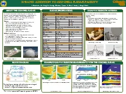
About the CSUCHILL Radar The CSUCHILL National Weather Radar Facility located in Greeley CO is an advanced transportable dualpolarized dualwavelength S and Xband weather radar system The facility is funded by the National Science Foundation and Colorado State University and is hoste ID: 185084

dual band wavelength radar band dual radar wavelength antenna feed chill csu facility phase addition offset features digital rain

Share:

Link:

Embed:

Download Presentation from below link

Download Presentation The PPT/PDF document "X-band" is the property of its rightful owner. Permission is granted to download and print the materials on this web site for personal, non-commercial use only, and to display it on your personal computer provided you do not modify the materials and that you retain all copyright notices contained in the materials. By downloading content from our website, you accept the terms of this agreement.


Presentation Transcript

Slide1

X-band

About the CSU-CHILL Radar

The CSU-CHILL National Weather Radar Facility, located in Greeley, CO, is an advanced, transportable dual-polarized, dual-wavelength (S- and X-band) weather radar system. The facility is funded by the National Science Foundation and Colorado State University, and is hosted by the Departments of Atmospheric Science and Electrical and Computer Engineering.

Features

Dual offset, dual-wavelength low

sidelobe

Gregorian antenna system

Easy-to-use, remotely accessible radar control interface

Polarization-agile dual-Klystron 1 MW transmitter at S-band

Simultaneous-transmit 25 kW Magnetron transmitter at X-band

Dual-channel software-defined digital-IF receiverFlexible signal processor, customizable to project needsComprehensive calibration subsystemVCHILL Real-time control and distribution of radar dataX-Band AdditionIn 2012, a dual-wavelength feed assembly and X-band transmit/receive subsystem were added to the radar systemThe dual-wavelength system expands the measurement capability of the radar to observe the full lifecycle of precipitationThis poster presents the technical description of the dual-wavelength feed, the X-band addition and some preliminary dual-wavelength measurements from this new addition

CSU-CHILL Radar Site

Radar Specifications

Dual-wavelength antenna

Example

Dual-Wavelength Measurements

with the CSU-CHILL radar

This facility is sponsored by NSF cooperative agreement no: AGS1138116

The CSU-CHILL radar features a unique dual offset-feed antenna with dual-wavelength capability

Features

Three feed horn options available (Dual wavelength, 10 cm and 3 cm)

Beam width of 1.0 degree at 10 cm (S-band), 0.3 degree at 3 cm (X-band)

Symmetric OMT design, with LDR limit exceeds 40 dBLow sidelobe levels improve clutter rejection at low elevation sweepsFlexible antenna controller supports sector scans and RHIs

Dual Reflector Assembly

Dual-wavelength Feed Assembly

X-band Antenna Pattern

Dual-wavelength measurements in snow

Parameter

S-band

X-band

Antenna

Type

8.5 meter dual-offset Gregorian parabolic reflector,Feed TypeScalar, symmetric OMTGain43 dBi53 dBiBeam Width1 degree0.3 degreeMax Sidelobe (one-way)< -27 dB< -36 dBPeak cross-pol< -43 dB< -23 dBScan typePPI (360°, sector), RHI, Fixed pointing, Vertically pointingMax. Slew Rate18 degrees/secTransmittersOperating Frequency2.725 GHz9.41 GHz +/- 30 MHzTypeDual KlystronMagnetronPeak power1 MW (per polarization)25 kWTransmit Mode (s)Single-pol, Simultaneous, AlternatingSimultaneousMax. Duty Cycle0.16 %0.16 %Max. PRF1.25 kHz2 kHzReceiversSensitivity-10 dBz at 30 km-10 dBz at 30 kmNoise Figure3.4 dB< 4.5 dBDynamic Range80 dB90 dBRange Resolution30 – 150 m1.2 – 192 mSignal Processing and ProductsProcessing ModesPulse Pair, Spectral Clutter Filter, Second Trip SuppressionPolarization ProcessingHydrometeor ID, attenuation correction, KDP estimationData ProductsZ, ZDR, V, W, ρHV, NCP, ϕDP, KDP, SNR

X-Band Addition to CSU-CHILL Radar facility

V. Chandrasekar, V.N. Bringi, S.A. Rutledge, D. Brunkow, F. Junyent, M. Galvez, P. Kennedy, J. George, R.Bowie

Block Diagram

The block diagram shows how the S- and X-band systems are integrated

S-band T/R, digital receiver located in radar van

X-band T/R, digital receiver mounted behind the antenna

Air-supported Radome

S-band Antenna Pattern

Differential Propagation Phase in Ice

X-band

S-band

S-band

Propagation phase at X-band

has three times more sensitivity than at S-band. This is useful when measuring

phidp

gradients in winter storm and light rain cases, where the phase shifts at S-band are low, and cause errors in slope estimation. This extends phase-based rain-rate estimation to low rain rates (less than 3 mm/

hr

), and allows observation of regions of oriented ice crystals.

Higher angular resolution at X-band

shows enhanced detail of fine structures in winter data

X-band

S-band

PPI Scan in Winter Storm

Improved angular resolution at X-band due to the finer beam width available