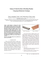
/
ISSN    Volume  ssue    Enhance Production Rate f Brai ISSN    Volume  ssue    Enhance Production Rate f Brai

ISSN Volume ssue Enhance Production Rate f Brai - PDF document

pamella-moone
pamella-moone . @pamella-moone
Follow
397 views
Uploaded On 2015-05-09

ISSN Volume ssue Enhance Production Rate f Brai - PPT Presentation

Kumbhalkar Sachin V Mate Sushama Dhote Mudra Gondane 12 HSDUWPHQWRI0HFKDQLFDOQJLQHHULQJ5V8PUHUFROOHJHRIQJLQHHULQJ8PUHU Dist Nagpur Maharashtra India Department of Mechanical Engineering Bhagwati Chaturvedi College of Engineering Nagpur Maharashtra I ID: 63581

Kumbhalkar Sachin Mate

Share:

Link:

Embed:

Download Presentation from below link

Download Pdf The PPT/PDF document "ISSN Volume ssue Enhance Producti..." is the property of its rightful owner. Permission is granted to download and print the materials on this web site for personal, non-commercial use only, and to display it on your personal computer provided you do not modify the materials and that you retain all copyright notices contained in the materials. By downloading content from our website, you accept the terms of this agreement.


Presentation Transcript

ISSN : 2319 – 3182, Volume - 2 , I ssue - 2 , 201 3 55 Enhance Production Rate o f Braiding Machine Using Speed Reduction Technique 1 Manoj A. Kumbhalkar, 2 Sachin V. Mate, 3 Sushama Dhote & 4 Mudra Gondane 1,2 Department of Mechanical Engineering, B.C.Y.R.C’s Umrer college of Engineering, Umrer, Dist Nagpur, Maharashtra (India) 3 Department of Mechanical Engineering, Bhagwati Chaturvedi College of Engineering, Nagpur, Maharashtra (India) 4 Department of Mechanical Engineering, Priyadarshini College of Engineering, Nagpur, Maharashtra (India) E - mail : manoj.kumbhalkar@rediffmail.com 1 , sushama170888@gmail.com 3 Abstract – Textile designing is a technical process which includes different methods for production of textile, surface design and structural design of a textile. Braid is the textile product having various types like round and flat braid made by using textile threads or wires which are alternative ly interwoven in braiding machine. A small scale industry in Nagpur produces each type of cotton braids using 16 spindle braiding machines on the single line shaft acquired power from 0.50 HP motor runs at 1440 rpm with the production rate of 87.5 m/hr. Th is paper discusses about to increase production of braids and design parameters of braiding machine. The production rate has been improved by modifying the some parameters by maintaining quality of braid as per the today’s market is concerned. Keywords: - b raid, braiding machine, drives, production rate, spur gear, speed reduction I . INTRODUCTION There is lot of textile products in market one of them is braided products like coated wire, yarns, plastic coatings etc. Braids are textile compositions made wit h yarn thread crossing in diagonal direction. Each thread intertwines the diagonal threads it crosses one from above and one from below. Braiding machines are used for such type of constructions. Braiding machines are used for producing wide range of arti cles viz. Round braid(cords, laces, cables or ropes) and flat braid (decorative objects, and hairstyles) shown in figure 1 and figure 2 using textile threads or wires which are alternatively interwoven . Figure 1 Round Braid Figure 2 Flat Braid The small scale industry in Nagpur produces round and flat braids of cotton and nylon material using 16 spindle braiding machines focus on to improve the production rate. 10 - 15 machines operate on single line shaft acquired p ower of 0.5 HP from electric motor and rotate at 1440 rpm with the capacity of 700 meter per day. The machine is constructed with the arrangements of spur gear, bevel gear, worm gear, horn gear, top plate and belt drives. Thread bundles (bobbins) has been mounted on the each spindle on the top plate having path for spindle carrier and the threads from each bobbins collected and carried by thread carrier on the top of the machine to form the braid as final product used for the laces of shoes, coating on elec tric wire, small size ropes. A. Observation During study in the industry about the production of braid, following points were observed: 1. Capacity of braiding machine to produce braid is about 700 meter per day from each machine. International Journal on Theoretical and Applied Research in Mechanical Engineering (IJ TARME ) ISSN : 2319 – 3182, Volume - 2 , I ssue - 2 , 201 3 56 2. Multiple machines operate on p ower of single motor (0.5HP) using line shaft. 3. On increasing the number of bobbins, thickness of final product is increases. 4. Total 60 machines are used for the continuous production of 4200 - 4500 meter per day for 8 - 10 hours. 5. For increasing the thickness of thread, the additional thread is provided from the centre of top plate as a central cord. II. WORKING PRINCIPLE OF BRAIDING MACHINE Braiding machine consist of component like electric motor, flat belt pulley, gears (bevel gear, horn gear, spur gear), rig - pick arrangement, thread carrier, spindles, top plate etc. Horn gears are mounted on the spur gears rotated below the top plate to drive yarn bobbins mounted over it. Each horn gear consists of four „wings’ that can accommodate one bobbin and the bobbin motion is prescribed through the groves in the top plate. Th e motion of yarns on one track is clockwise and the other is counter clockwise causing the yarns to interlace. The track plate consists of two separate paths: each path 180 degrees out of phase from the other. One path motion is clockwise, while the other path is counter clockwise; at the point where the paths converge, the yarns interact as one yarn travels over and the other yarn under. The over - under interaction causes an interlacing of the two yarns and is the chief mechanism responsible for the formati on of the braided structure. The braid is formed as a continuous process by interlacing the yarns and drawing them through a „braiding point’. The mounting of bobbins on spindle and rotation of horn gears are shown in figure 3 . Figure 3 Rotation of bob bins due to horn gear Groves in the top plate also guide the bobbins; however, switch points are located between each pair of horn gears that can be activated to transfer the bobbin to an adjacent horn gear. In braiding machine the top plate is intended w ith the path of spindle carrier as through which the spindle followed forward and reversed motion. The interlocked threads pulled up with the help of rig - pick arrangement. M. Schneider et al 4 explain the motion of bobbins due to rotation of horn gears. Fig ure 4 shows the driving path of bobbins on the top plate and figure 5 explain the driving mechanism . Figure 4 : Photo of Top plate showing driving path of bobbins Figure 5 : Driving Mechanism of machine The power of 0.5 horse power is first transmitted by the electric motor with the speed of 1440 rpm to the line shaft via V - belt drive which tansfer the power to the horizontal shaft of braiding machine via flat belt drive. Bevel gear is mounted on the same shaft of larger flat belt pulley rotates with same speed and transmitted power to the vertical shaft where the spur gear is fitted with bevel gear which rotates the horn gears and provide International Journal on Theoretical and Applied Research in Mechanical Engineering (IJ TARME ) ISSN : 2319 – 3182, Volume - 2 , I ssue - 2 , 201 3 57 motion to bobbins mounted on the top plate by transmitting the powe r to the gear train assembled below the top plate. The vertical shaft is attached with the worm and worm gear from which the power is transmitted to the rig - pick arrangement (spur gear drive) which plays an important role in production of braiding machine. The braid carries by the thread carrier (Spur gear drive) at the top depend on the speed of rig - pick arrangement. Therefore by incresing the speed of shaft between thread carrier and rig - pick arrangement the production of machine can be increased by maint aining the speed ratio to maintain the quality of braid. Figure 6 and 7 shows the actual photo and schematic diagram of braiding machine . Figure 6 : Photograph of Braiding machine Figure 7 : Schematic diagram of Braiding machine III. SPEED REDUCTION I N BRAIDING MACHINE By study of the components and working of braiding machine it is observed that speed (in rpm) is main factor responsible for the production of braid. The speed is reduced from electric motor to thread carrier by the various arrangements of drives in the machine as per the requirements which is responsible for the production of braid. Table 1 shows the technical specification of the components of braiding machine. Table 1 Technical specifications of components of braiding machine Particu lars Unit Dimensions Spindle - 16 Pitch Size mm 3 Motor Power HP 0.5 Weight Kg 650 Length mm 1650 Width mm 1000 Height mm 1600 Diameter of V - Belt Driver pulley mm 50.8 Diameter of V - Belt Driven pulley mm 457.2 Diameter of Flat belt driver and driven pulley mm 127 Teeth on Spur Gear drive of top plate - 32 Teeth on Bevel Gear - 21 No. of teeth on worm and worm gear - 4 & 24 Teeth on Spur Gear of rig - pick arrangement (larger& smaller) - 60 & 45 With the help of technical specification of the components of braiding machine, speed in rpm of each components has been calculated using relation N 1 D 1 =N 2 D 2 or N 1 T 1 =N 2 T 2 which finds the speed ratio of 4.45. Where N 1 & N 2 are the speed of driver and driven shaft, D 1 & D 2 are the diameter of driver and driven pulley and T 1 & T 2 are the number of teeth on driver and driven gear. By maintaining the same speed ratio production of machine has been increased by replacing the spur gear of rig - pick arrangement as per the av ailability. The speed in whole arrangement is reduced from 1440 rpm to 36 rpm which gives the production of 700 m/day for each machine. The calculated value of speed of each component of the braiding machine is shown in table 2. International Journal on Theoretical and Applied Research in Mechanical Engineering (IJ TARME ) ISSN : 2319 – 3182, Volume - 2 , I ssue - 2 , 201 3 58 Table 2 : Speed Reduction in Braiding Machine Sr. No. Drives Speed (rpm) Driver Driven 1 V - belt drive 1440 160 2 Flat belt drive 160 160 3 Bevel gear drive 160 160 4 Spur gear drive (Top plate) 160 160 5 Worm & worm gear drive 160 27 6 Spur gear drive (rig - pick arrangement) 27 36 The speed is varies from top plate to rig - pick arrangement (or pulling system) which gets the speed ratio of machine . A. Analytical modification of machine parameter to increase production As the speed of shaft between pulling system and rig - pick arrangement is mainly responsible for the production, it is necessary to increase speed of that shaft to improve production by maintaining the quality of braid which has been obtained by maintaining the same speed ratio and calculate or redesign other parameters of braiding machine. Accordingly, the speed of top plate also increased which relieves thread to pulling system. To increase speed, the small gear with 45 teeth in the rig - pick arrangement has been replaced with the gear of 35 or 24 teeth as per the availability for the machine in industry. Accordingly the size of worm gear and flat belt pulley has been modified. To check the production of single braiding machine V - belt and flat belt drive is replaced with on ly flat belt drive. The calculations for 35 and 24 number of teeth are as follows: For the power of 0.5 HP with motor speed N 1 =1440 rpm, modify the parameter of components of braiding machine for two cases considered for rig - pick spur gear arrangement. Cas e I: If T g = 60, N g = 27 keep unchanged & T p = 35 from 45 N g T g = N p T p N p = 47 rpm With respect to velocity ratio=4.45& speed of smaller spur gear= 47 rpm Speed of top plate spur gear, N 2 = 47 × 4.45 N 2 =209 rpm To enrich the speed of 27 rpm to driver rig - pick spur gear, the worm gear has to be replaced with 31 numbers of teeth. From table 2, it is cleared that the speed of larger flat belt pulley is equal to the speed of top plate spur gear, therefore the diamete r of the larger flat belt pulley can be modified and calculated using relation, N 1 × D 1 = N 2 ×D 2 (D 1 = 50.8mm, from table 1) D 2 =350 mm (14 inch) Accordingly, the production rate has been changed as the speed of pinion is increased from 36 rpm to 47 rpm. For N p =36 rpm , production rate is 87.5 m/hr. So for N p =47 rpm, Production rate = (87.5/36) × 47 = 114.24 m/hr. By replacing the spur gear of 45 teeth with 35 teeth the production rate has been increased to 114.24 m/hr Case II: If T g = 60, N g = 27 keep unchanged & T p = 24 from 45 N g T g = N p T p N p = 67.5 rpm With respect to velocity ratio=4.45& speed of smaller spur gear= 67.5 rpm . Table 3 comparison between existing and modified machine Braiding machine Speed of motor (rpm) V - belt Pulley Diameter (mm) Flat - belt Pulley Diameter (mm) Teeth on Worm & Worm Gear Teeth on spur gear of rig - pick arrangement Producti on rate (m/hr) Driver Driven Driver Driven Worm Worm gear Gear Pinion Current machine 1440 50.8 457.2 127 127 4 24 60 45 87.5 Modified machine 1440 - - 50.8 350 4 31 60 35 114.24 - - 50.8 244 4 45 60 24 164 International Journal on Theoretical and Applied Research in Mechanical Engineering (IJ TARME ) ISSN : 2319 – 3182, Volume - 2 , I ssue - 2 , 201 3 59 . Speed of top plate spur gear, N 2 = 67.5 × 4.45 N 2 = 300 rpm To enrich the speed of 27 rpm to driver rig - pick spur gear, the worm gear has to be replaced with 45 numbers of teeth. Similarly the diameter of larger gear and production rate for the speed of 67.5 rpm is calculated and compared with previous one. N 1 × D 1 = N 2 ×D 2 (D 1 = 50.8m m, from table 1) D 2 = 244 mm (9.6 inch) For N p =36 rpm , production rate is 87.5 m/hr. So for N p =67.5 rpm, Production rate = (87.5/36) × 67.5 = 164 m/hr. By replacing the spur gear of 45 teeth with 24 teeth the production rate has been increased to 164 m/hr . From the calculation it is observed that the production rate is increased by replacing the smaller spur gear of rig - pick arrangement and modifying some parameters of components of braiding machine. The comparison of production rate and other technic al design parameter of existing and new machine is shown in table 2. IV. CONCLUSION After the Study of company profile, braiding machine and its components and company profile, it is observed that the braid plays an important role in textile engineering and useful for the laces, coating on wires etc. From company profile and market demand it is necessary to improve the production rate to achieve the demand. Each component of braiding machine and it’s principle of working is studied well in order to get technical logic to improve the production rate. After analytical study of each component and its technical parameters it is conclude that the speed reduction is the main factor affecting the production rate. The current braiding machine gives the production of 87.5 m/hr for 8 hours per day which is increased to the level of 164 m/hr after the modification of some parameters analytically. To increase the production rate, the smaller spur gear of rig - pick arrangement has been replaced from 45 number of teeth to 35 and 24 number of teeth. The production rate has been calculated for both the cas es and it is observed that it is more in the replacement with 24 teeth gives the production rate of 164 m/hr by maintaining the quality of braid. Accordingly, the other parameters also affected and changed as per the details mentioned in table 3. After the modification production rate is increased and satisfies today’s market demand. V. REFERENCES [1] Juha - Pekkanuutinen, Claude Clerc, Raija Reinikainen and Pertti tormala, “Mechanical properties and in vitro degradation of bioabsorbable self - expanding braided st ents”, J. Biomater. Sci. Polymer Edn, Vol. 14, No. 3, pp. 255 – 266, 2003. [2] David John Branscomb, Royall M. Broughton, David G. Beale, “A machine vision and sensing system for braid defect detection, diagnosis and prevention during manufacture”. [3] Tadashi Uozum and Masao Hirukawa, “Braiding technologies for commercial applications”, 6th Japan International SAMPE Symposium & Exhibition (JISSE - 6) Tokyo Big Sight, Tokyo, Japan, 1999. [4] M. Schneider, A. K. Pickett and B. Wulfhorst, “New rotary braiding machine and CAE procedure to produce efficient 3 - d textiles for composite” 45 th SAMPE international symposium, Long Beach CA, USA. 2000. [5] J.H. van Ravenhorst and R. Akkerman, “A spool pattern tool for circular braiding”, 18th international conference on composite material s. [6] B. C. Giltgren and A. Kashem, “Experiences with manually operated net - braiding machine in Bangladesh”, Development of Small - Scale Fisheries in the Bay of Bengal. BOB P/WP/50, 1986. [7] P. Potluri, A. Rawal, M. Rivaldi, I. Porat, “Geometrical modelling and c ontrol of a triaxial braiding machine for producing 3D performs”, Composites part - A: applied science and manufacturing, science direct, Composites: Part A 34 (2003) 481 – 492, 2003.   