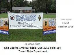
Tuned Stubs Experiment Sam Stello KK4VR October 2015 Problem Statement The energy from a typical HAM radio transmitter when another radios antenna is in close proximity can couple into ID: 673649
Download Presentation The PPT/PDF document "Lessons from King George Amateur Radio C..." is the property of its rightful owner. Permission is granted to download and print the materials on this web site for personal, non-commercial use only, and to display it on your personal computer provided you do not modify the materials and that you retain all copyright notices contained in the materials. By downloading content from our website, you accept the terms of this agreement.
Slide1
Lessons fromKing George Amateur Radio Club 2015 Field DayTuned Stubs Experiment
Sam StelloKK4VROctober, 2015Slide2
Problem StatementThe energy from a typical HAM radio transmitter, when another radio’s antenna is in close proximity, can couple into
the second radio and cause interference even if they are widely separated in frequency. In the extreme, the front end of the victim radio can be seriously damaged.
Ham radio receivers
can
be
overdriven and damaged by EMI!Slide3Slide4
Our Field Day Interference ProblemAt our FD the last two years, we had severe cross band interference
We were working HF bands, CW and Voice on 10, 15, 20, 40, and 80 meter bandsWe had disabling interference between 15 and 20 mtr CWPower used was under 100 watts (50 typical)
We decided to investigate RF filtering solutions for 20/15
mtr
interference for this year’s FD
Physically separating antennas had limited effectiveness because of FD site Slide5
2015 Field Day Antenna Plan
Estimated Coax Runs:Dipole 160 ft 2 Mtr 0 ftInv
-V 20-15 100
ft
Moxon
15 50
ftInv-V 20-15 135 ft
Moxon 20 80 ftInv
-V 40 50 ft Vertical 40 135 ft
NOTE: All measurements to trees are approximate distances to base; branches will subtract from available antenna distances
Pavilion
American Legion
Building
Shed
Grill
East
South
West
North
p
arking
Driveway
Driveway
Route 206
145
ft
cementary
Gun Monument
p
ower line
Pit
MOXON 20
mtr
MOXON 15
mtr
Vertical 40
mtr
Inv
-V 40
mtr
Inv
-V 20-15
mtr
Inv
-V 20-15
mtr
Dipole 80-10
mtr
Generators
2
mtrSlide6Slide7
Should We Use Bandpass Filters?
Issues:Tuning external filters to match radio’s frequency and adjusting filter bandwidth according to band being used is difficult over wide frequency rangesIt is difficult to match input and output impedances to 50 ohms over very wide frequency rangesBandpass filters’ rejected signals will reflect back to the antenna and radio!
This is a difficult approach to implementSlide8
Solving the problem withBand Reject Filters
Band Reject filters effectively short the feedline on HAM bands not being used; filters present “high impedance” to band in useFilters work for signals in both directions, ie, both transmitted and received signals are passed or rejected according to filter settings
Requires a filter for each band
rejected, but we can take advantage of the limited number of HF Field Day bands
Band 2,3,4,5 filters
Band 1Slide9
Commercial Filter ProductsSingle Band Lumped C
omponent HF RF filters Typically 25 db of suppression (4 + S Units)Filters are fixed frequency, single Ham band filtersInternet user reviews very favorable
Issues:
Manual band
s
witching required
Filters made to order; lead
time can be several monthsPower limitations; filters can be destroyed by too much powerCost is approximately $120 each band; one HF 5 band set can cost $600
“homebrew designs” available, but internet reviewers warned about difficulty to build and tune; parts availability is also a concern
Many Hams who purchased commercial filters were pleased with their purchaseSlide10
¼ Wave Tuned Stub Alternative Approach
A RF filter can be built from common coax A ¼ wave coax stub at the tuned frequency will invert the impedance at the opposite end of the cable.Assume one end of a coax is open. Then the current at that end is nearly zero (less leakage);
at the other end of the coax, ¼ wave away, the current must be very high.
The
inverse
is true for the voltage.
THEREFORE:
Since Z = E / I, the impedance at the open end must be very high and the impedance at the opposite end is very low at the tuned frequency
.The inverse
happens for an shorted coax stub, that is, the impedance at the opposite end is very high at the tuned frequency.Slide11
Impedance Transformation in aCoax Stub with the Open Circuit End
Current at open cable end
Voltage at open cable end
Voltage at ¼ wavelength
Current at ¼ wavelength
Z = E / I
High Z
Low ZSlide12
Tuned Stub Filter Design
Physical length of cable is calculated for ¼ wave as:
Length
feet
= (Velocity Factor x 983.6) / 4
Freq
MHZ
Length is approximate; cut longer and trim to resonance
Coax to Radio
Coax to antenna
RG8 or other HF grade coax
End of cable is open circuited
Coax “T” connector
PL259
PL259Slide13
Multiple Tuned Stub Filters Example
Here is an example of two filters used to reduce interference from two adjacent bands (NOTE: other radios may still have to install their own filters)
Example
from AC0C Amateur Radio article on So2R “targeted Attenuation for Adjacent Bands” http://ac0c.com/main/page_so2r_coax_stub_intro.html
40
mtr
20
mtr
80
mtrSlide14
Copied from AC0C Amateur Radio article on So2R
“targeted Attenuation for Adjacent Bands” http://ac0c.com/main/page_so2r_coax_stub_intro.html
Two tuned stub filters at 80 and 20 meters
for a radio operating on 40 meters
HERE IS THE 20 MTR TUNED STUBSlide15
Copied from AC0C Amateur Radio article on So2R
“targeted Attenuation for Adjacent Bands” http://ac0c.com/main/page_so2r_coax_stub_intro.html
Two tuned stub filters at 80 and 20 meters
for a radio operating on 40 meters
HERE IS THE 80 MTR TUNED STUBSlide16
Our Field Day ExperimentWe built three “40 mtr
tuned stub” filters using “junkbox” parts and coaxCost was 25 feet of coax, a RF “T” connector , two PL259 and one SO239 connector per radioCost would be approximately $50 for each radio, if built with new components
Actuals were approximately $20 for each radio using old coax, toolbox connectors plus some new connectors
Bottom Line: our interference problem was solved at much less cost than purchasing commercial filters!Slide17
Our Field Day Tuned Stub Filter Design
Physical length of cable is calculated for ¼ wave as:
Length
feet
= (VF x 983.6) / 4
Freq
MHZ
¼ wave stub of RG 8 at 40 meters would be: (0.66x983.6) / (4 x 7MHZ) =23.2 feet
When trimming, a change of approximately 4 inches in cable length corresponds to 100khz at 7 Mhz
to Radio
to AntennaRG8 or other HF grade coaxScrew bulkhead connector into PL259 for “Open”
Remove connector for “short”
SO239 with center pin shorted to case
PL259
PL259
Coax “T” connectorSlide18Slide19
Coax Impedance Transformation1. A ¼ wave coax at the tuned frequency will inverse the impedance present at the opposite end of the cable.
2. A ½ wave coax at the tuned frequency will have the same impedance as present on the opposite end of the cable.3. A ¾ quarter wave coax at the tuned frequency will
act like a ¼ wave coax, that is, it will inverse
the impedance
present at
the opposite end of the cable
.
4. A full wave coax at the tuned frequency will act like a half wave coax, that is, it
will have the same impedance as present on the opposite end of the cable.5. This pattern repeats beyond one wavelengthSlide20
Impedance Transformation in a Coax Stub with the end shorted
Voltage at shorted cable end
Current at shorted cable end
Current at ¼ wavelength
Voltage at ¼ wavelength
Z = E / I
Low Z
Low Z
High Z
High ZSlide21
Summary
Cable LengthStub Impedance at Radio and Antenna cable end
Open cable end configuration
¼ wave
High Impedance
shorted
Low Impedance
opened
1/2 wave
Low Impedance
shorted
High Impedanceopened¾ waveHigh Impedanceshorted
Low Impedance
openedFull wave
Low Impedance
shorted
High ImpedanceopenedSlide22
Our “Poor Man” Approach to Multiple Filters
The amateur HF ham bands are harmonically related, so A quarter wave stub on 40 mtrs is a half wave stub on 20 mtrs!
Etc
,
etc
, etc.
Therefore,A shorted ¼ wavelength stub on 40 meters appears as:High Impedance on 40 and 15 mtrs
Low Impedance on 20 and 10 mtrsAn open ended ¼ wavelength stub on 40
mtrs appears as:Low Impedance on 40 and 15 mtrsHigh Impedance on 20 and 10
mtrsSlide23
Harmonic Relationships of HF Bands
35 feet is:
¼ wavelength on 7.02
mhz
35
ft
(free space)
1/2 wavelength on 14.05
mhz
1
wavelength on 28.1
Mhz
3/4 wavelength on 21.075
mhz
40m
2
0m
15m10mSlide24
Effects on HF Ham Bands of a 40 mtr ¼ Wave Tuned Stub
Band
Shorted Stub
Open Stub
80
-------
------
40
passshort
20short
pass15pass
short10shortpassSlide25
Our FD Interference Situation
15
mtr
2
0
mtrSlide26
Assumed Interference Mechanism
14MHz
7
MHz
21MHz
28MHz
3.5MHz
20
mtr
transmitter
14MHz
7
MHz
21MHz
28MHz
3.5MHz
15
mtr
receiverSlide27
Our First FD Attempt at Filtering
15
mtr
2
0
mtr
Stub end openSlide28
Effects of 40 mtr Tuned Stub on20 mtr
Transmitter
14MHz
7
MHz
21MHz
28MHz
3.5MHz
20
mtr
transmitter
14MHz
7
MHz
21MHz
28MHz
3.5MHz
15
mtr receiverSlide29
Our Second Attempt at FD Filtering
15
mtr
Stub end shorted
2
0
mtr
Stub end openSlide30
Effects of 40 mtr Tuned Stub on Transmitter and Receiver
14MHz
7
MHz
21MHz
28MHz
3.5MHz
20
mtr
transmitter
14MHz
7
MHz
21MHz
28MHz
3.5MHz
15
mtr
receiverSlide31
Our Field Day Tuned Stub Configuration The offending 20
mtr transmitter was effectively isolated
15
mtr
Stub end shorted
2
0
mtr
Stub end open
40
mtr
Stub end shortedSlide32
Lessons Learned (1)
Tuned Stub Filters are Easily DesignedCalculations are simpleHarmonic relationships must be considered in all designs, even single band filtersFor multi-band single stub designs, band chosen must be at lowest affected frequencyTuned Stubs are E
asily
B
uilt
Fast to
build
Easy to tune with an antenna analyzerEasy to testBe careful about the quality of the coax; some old contaminated coax has very different velocity factors Types of center insulation of coax limits loop sizes (avoid foam centers)Slide33
Lessons Learned (2)Tuned Stubs Require
Thoughtful HookupsCare must be taken to ensure correct configuration for band in use…don’t short out your transmitter!Danger! There is very high voltages on the open cable
ends
¼ wave stubs only work well on higher frequency
bands
Our
40
mtr stubs would not work well with
Interference on 80 or 160 mtr bands!Slide34
Why doesn’t a 40
mtr stub work well on 80?
35 feet is
¼ wavelength on 7.02
mhz
35 feet (free space)
35 feet is
1/8 wavelength on 3.51
mhz
A
40
mtr
stub will not work well on
80but A 80
mtr ¼ wave stub will work well on 40 and higher bands!
HOWEVER: ¼ wavelength on 80 is ½ wavelength on 40!Slide35
Lessons Learned (3)At field day
Using a filter on each of the interfering radios made some happy and pleasantly surprised operatorsUsing a single filter on one radio was insufficientTwo filters on the same radio during bench testing provided 3 dB additional
suppression for one coupling mechanism,
but
overall effect was
hardly noticeable!
Filter on the second radio was used to knock out second coupling
Filter Bandwidths covered
our bands of interest with 4+ S units reduction per filter
As long as we stayed on a single band, the filters did not negatively affect our operations; switching bands required minor reconfigurationsSlide36
SummaryOur filter approach was effective for selected crossband combinations; not useful for all band interference combinations (we knew that going in
)Tuned Stubs may not be the best EMI filter solution, but were very cost effective in our application!Band harmonic relationships in tuned stubs can work for and against you
At next FD,
we may experiment with more tuned stub
filtersSlide37