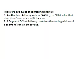
1 An Absolute Address such as 04A26H is a 20 bit value that directly references a specific location 2 A Segment Offset Address combines the starting address of a segment with an offset value ID: 130831
Download Presentation The PPT/PDF document "There are two types of addressing scheme..." is the property of its rightful owner. Permission is granted to download and print the materials on this web site for personal, non-commercial use only, and to display it on your personal computer provided you do not modify the materials and that you retain all copyright notices contained in the materials. By downloading content from our website, you accept the terms of this agreement.
Slide1
There are two types of addressing schemes:
1. An Absolute Address, such as 04A26H, is a 20 bit value that
directly references a specific location.
2. A Segment Offset Address, combines the starting address of
a segment with an offset value.Slide2
Segments and Addressing
Segments are special area defined in a program for containing
the code
, the data, and the stack.
Segment Offset within a program,
all
memory
locations within a segment are relative to the
segment starting
address. The distance in bytes from the segment address
to another
location within the segment is expressed as an
offset (
or
displacement
).
To reference any memory location in a segment, the
processor combine
the segment address in a segment register with the
offset value
of that location, that is, its distance in byte from the start
of the
segment.
Specifying addresses
To represent a segment address and its relative offset we use
the notation
:
Segment: offset
Thus
020A:1BCD denotes offset 1BCDH from segment 020AH.
The actual address it refers to is obtained in the following way:
1- Add zero to the right hand side of the segment address.
2- Add to this the offset.
Hence the actual address referred to by 020A:1BCD is 03C6D.Slide3Slide4
Address Bus in the
8086 is 20 bits wide (20 lines) i.e. the
processor
can
access memory of size 2
20
or 1048576 bytes (
1MB).
Instruction Pointer = 16 bit register which means the processor
can only
address 0 – 2
16
(65535) bytes of memory. But we need
to write
instructions in any of the 1MB of memory. This can
be solved
by using memory segmentation., where each
segment register
is 16-bit (this 16-bit is the high 16-bit of Address Bus (
A
4
- A
19
)) i.e. each of the segment registers represent the actual
address after
shifting the address 4-bit to get 20 bits.Slide5
Number of Operands
Operands specify the value an instruction is to operate on,
and where
the result is to be stored. Instruction sets are classified
by the
number of operands used. An instruction may have no,
one, two
, or three operands.
1. three-Operand instruction:
In instruction that have three operands, one of the
operand specifies
the destination as an address where the result is to
be saved
. The other two operands specify the source either
as addresses
of memory location or constantsSlide6
EX: A=B+C
ADD
destination, source1,
source2
ADD
A,B,C
EX
: Y
=(X+D)* (N+1)
ADD
T1, X, D
ADD
T2, N, 1
Mul
Y, T1, T2
2. Two operand instruction
In
this type both operands specify sources. The first operand
also specifies
the destination address after the result is to be saved.
The first
operand must be an address in memory, but the second may
be an
address or a constant.
ADD
destination, source
EX:
A=B+C
MOV A, B
ADD A, C
EX: Y=(X+D)* (N+1)
MOV T1, X
ADD T1, D
MOV Y, N
ADD Y, 1
MUL Y, T1Slide7
3. One Operand instruction
Some computer have only one general purpose register,
usually called
on Acc. It is implied as one of the source operands and
the destination
operand in memory instruction the other
source operand
is specified in the instruction as location in memory
.
ADD
source
LDA
source; copy value from memory to ACC.
STA
destination; copy value from Acc into memory.
EX:
EX
:
A=B+C Y
=(X+D)* (
N+1)
LDA
B
LDA
X
ADD C
ADD D
STA A
STA T1
LDA
N
ADD
1
MUL
T1
STA
Y
4. Zero Operand instruction
Some computers have arithmetic instruction in which all
operands are
implied, these zero operand instruction use a stack, a stack is
a list
structure in which all insertion and deletion occur at one end,
the element on a stack may be removed only in the reverse of
the order
in which they were entered. The process of inserting an
item is
called
Pushing, removing an item is called Popping.Slide8
Computers that use Zero operand instruction for
arithmetic operations
also use one operand
PUSH and POP instruction
to
copy
value between memory and the stack.
PUSH source; Push the value of the memory
operand
onto
the Top of the stack.
POP destination; POP value from the Top of the
stack
and
copy it into the memory operand
.Slide9Slide10
The 8086 Addressing Mode
When the 8086 executes an instruction, it performs the
specified function
on data. Thee data are called its
operands and may
be
part
of the instruction reside in one of the internal registers of
the 8086
, stored at an address in memory, or held at an I/O port.
To access
these different types of operands, the 8086 is provided with
various
addressing modes:
1. Register Addressing
Mode:
With
the register addressing mode, the operand to be accessed is
specified as residing in an internal register of the 8086, an
example of
an instruction that uses this addressing mode
is MOV
AX, BX
This
stands for move the contents of BX, the source operand,
to AX
, the destination operand. Both the source and
destination operands
have been specified as the content of the internal registers
of the 8086. See Figure 10(a, b
).
2. Immediate Addressing
Mode:
If
a source operand is part of the instruction instead of the
contents of
a register or memory location, it represents what is called
an immediate
operand and is accessed using the immediate
addressing mode
. Typically, immediate operands represent constant
data. Immediate
operands can be either a byte or word of data. In
the instruction
MOV AL, 015H
The
source operand 15H is an example of a byte-wide
immediate source
operand. Note that the value of the immediate operand
must always
be preceded by a zero. See Figure 11(a, b).Slide11Slide12Slide13
3. Direct Addressing Mode
Direct
addressing differs from immediate addressing in that
the locations
following the instruction
opecode
hold an
effected memory
address (EA) instead of data. This effective address is
a
16-bit
offset of the storage location of the operand from the
current value
in the data segment (DS) register. EA is combined with
the contents
of DS in the BIU to produce the
physical address for
its
source
operand is
MOV CX, BETA
This
stands for move the contents of the memory location which
is offset
by BETA from the current value in DS into internal
register CX
. See Figure 12(a, b). Notice that the value assigned to constant
BETA is 1234H.
PA = 02000H +
1234H =
03234H
4. Register Indirect Addressing Mode
Register
indirect addressing is similar to direct addressing in
that an
effective address is combined with the contents of DS to
obtain a
physical address. However, it differs in the way the offset
is specified
. This time EA resides in either a pointer register or
index register
within the 8086. The pointer
register
can be either BX
or BP
and the index register can be SI or DI.
MOV AX, [SI]
This
instruction moves the contents of the memory location
offset by
the value of EA in SI from the current value in DS to the
AX register
. See Figure 13(a, b). SI contains 1234H and DS contains
0200H.
PA = 02000H +
1234H =
03234HSlide14Slide15Slide16
5. Based Addressing Mode
In the based addressing mode, the physical address of the
operand is
obtained by adding a direct or
indirect
displacement to
the contents
of either BX or BP and the current value in DS and
SS, respectively
. A MOV instruction that uses based addressing
to specify
the location of its destination operand is as follows:
MOV [BX].BETA, AL
As shown in Figure 14(
a,b
) the fetch and execution of
this instruction
causes the BIU to calculate the physical address of
the destination
operand from the contents of DS, BX, and the direct
displacement
. The result
is PA
= 02000H + 1000H +
1234H =
04234H
6. Indexed Addressing Mode
Indexed
addressing works identically to the based addressing,
it uses
the contents of one of the index registers, instead of BX
or BP
, in the generation of the physical address, here is an example:
MOV AL, ARRAY[SI]
The
example in Figure 15(
a,b
) shows the result of executing
the MOV
instruction. First the physical address for the source
operand is
calculated from DS, SI, and the
direct
displacement.
PA = 02000H + 2000H +
1234H=
05234H
Then the byte of data stored at this location, which is BEH is
read into
lower byte AL of the accumulator register.Slide17Slide18Slide19
7. Based Indexed Addressing Mode
Combining the based addressing mode and the indexed
addressing mode
together results in a new, more powerful mode known
as based
indexed addressing. Let
us consider
an example of a
MOV instruction
using this type of addressing.
MOV AH, [BX].BETA[SI]
An example of executing this instruction is illustrated in
Figure 16(
a,b
). The address of the source operand is calculated
as
PA
= 02000H + 1000H + 1234H +
2000H
=
06234H
Execution
of this instruction causes the Value stored at
this location
to be written into AH.
8. String Addressing Mode
The
string instructions of the 8086's instruction set
automatically use
the source and destination index registers to specify
the effective
addresses of the source and destination
operands, respectively
. The move string
instruction MOVS
is an example. Notice that neither SI nor DI appears in the
string instruction
, but both are used during its execution.Slide20Slide21
9. Port Addressing Mode
Port addressing is used in conjunction with the IN and
OUT instructions
to access input and output ports. Any of the
memory addressing
modes can be used for the port address for
memory mapped
ports. For ports in the I/O address space, only the
Direct addressing
mode and an Indirect addressing mode using DX
are
available
. For example,
Direct addressing of an input port is
used
in
the instruction
IN AL, 15H
This
stands for input the data from the byte wide input port
at address
15H of the I/O address space to register
AL. Next
, let us consider another example. Using
Indirect
port addressing
for the source operand in an IN instruction, we get:
IN AL, DX
It
means input the data from the byte wide input port
whose address
is specified by the contents of register DX. For instance,
if DX
equals 1234H the contents of the port at this I/O address
are loaded
into AL.